The Laser module is the part of Smoothie that allows you to control laser cutters.
In general, laser cutters use a CO2 tube to generate the laser beam used for cutting and engraving.
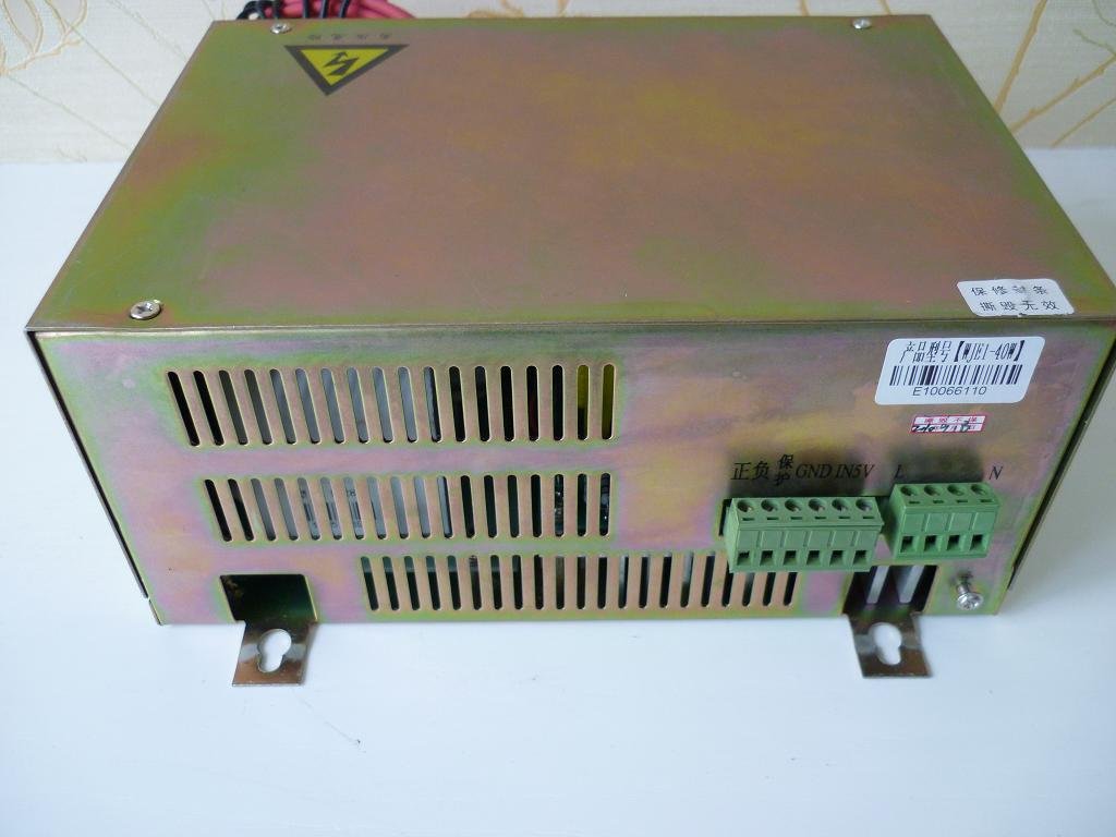
Those tubes contain CO2 gas, and a high-voltage Power Supply Unit is used to pass electricity through the gas, generating the beam.
Using G-code, you tell Smoothie where to move and when to cut. Smoothie moves the motors, and the Laser module talks to the laser power supply to tell it when to turn off and on, and using how much power.
Don't die
Be very careful with the laser tube side of your Power Supply : voltages there are commonly around 40 000 volts, making it very dangerous.
If you are not qualified to handle this kind of voltage, please contact a professional.
Always make sure everything is powered down before manipulating anything.
Wiring
In order to control the power of the laser tube, the laser PSU reads a PWM signal as it's input.
Please look at the datasheet for your PSU to know which connection that signal is wired to.
From the Smoothieboard, you need to connect :
- One GND pin to the Ground connection on the PSU
- One of Smoothie's PWM pins to the PWM input on the PSU
Both Ground pins are easy to find, and the PSU input you find in the manual/datasheet, now all you need is to find a PWM pin on the Smoothieboard.
There are 6 of them, but 4 of them are used for the step pins for stepper motor drivers.
Those for alpha and beta you won't be able to use as you use those drivers to control the X and Y axes.
Depending on whether you have a Z axis, your gamma axis step pin could be used. It is labelled ST3, on the JP12 header, near the M3 stepper motor driver.
You probably do not use your delta ( M4 ) stepper motor driver on a laser cutter, so that pin can also be used, it is labelled ST4 on the JP15 header near the M4 stepper motor driver.
The other two are found near the microcontroller and the MOSFETS, on the JP33 header, and are labelled PWM0 and PWM1.
Choose which you will use, all have a GND header close-by ( all are unlabelled ) to make it convenient for wiring.
Now you need to find which GPIO pin/port number corresponds to the PWM pin you chose, so you can tell Smoothie which you'll be using in the configuration file.
| Pin number for configuration | Label on the board | Comment |
|---|---|---|
| 2.2 | STP3 | Only if you are not using a Z axis/the gamma driver. Make sure you set gamma_step_pin to the "nc" value. The unlabelled pin in JP12 is GND. |
| 2.3 | STP4 | Only if you are not using the delta driver. Make sure you set delta_step_pin to the "nc" value. The unlabelled pin in JP15 is GND. |
| 2.4 | PWM0 | Only if you are not using the first small MOSFET ( X8 ). All pins of JP10 are GND. |
| 2.5 | PWM1 | Only if you are not using the second big MOSFET ( X15 ). All pins of JP10 are GND. |
Now that the PSU is wired to the Smoothieboard and that you know which pin you are using for control, you can change the configuration file to setup laser control
Configuration
You now need to edit the "config" file on the SD card ( the default configuration file already contains example laser lines so you may only need to edit/enable those ) to add or setup the laser part as follows :
# Laser module configuration
laser_module_enable                          true             # Whether to activate the laser module at all. All configuration is
                                                              # ignored if false.
laser_module_pin                             2.5              # this pin will be PWMed to control the laser. Only P2.0 - P2.5
                                                              # can be used since laser requires hardware PWM
#laser_module_max_power                       0.8             # this is the maximum duty cycle that will be applied to the laser
#laser_module_tickle_power                    0.0             # this duty cycle will be used for travel moves to keep the laser
                                                              # active without actually burning
#laser_module_pwm_period                      20              # this sets the pwm frequency as the period in microseconds
If needed, replace the 2.5 value for laser_module_pin with the pin you chose in the wiring section.
Save the file, reset the board, you are now ready for laser testing.
All options
| Option | Example value | Explanation |
|---|
| laser_module_enable | false | Whether to activate the laser module at all. All configuration is ignored if false. The laser module is used for laser cutting using a laser diode or CO2 laser tube. |
| laser_module_pin | 2.5 | This pin will control the laser. Pulse width will be modulated to vary power output ( PWM ). Note : PWM is available only on pins 2.0 to 2.5, 1.18, 1.20, 1.21, 1.23, 1.24, 1.26, 3.25 and 3.26 |
| laser_module_max_power | 0.8 | This is the maximum duty cycle that will be applied to the laser. Value is from 0 to 1 |
| laser_module_tickle_power | 0.0 | This duty cycle will be used for travel moves to keep the laser active without actually burning. Useful for some diode setups. Value is from 0 to 1 |
| laser_module_pwm_period | 20 | PWM frequency expressed as the period in microseconds |
Testing
First of all
Make sure your laser cutter enclosure is closed and that everything is safe.
Wear laser protection googles, even if the machine is properly closed.
Make sure your machine has a proper enclosure, and a switch on the door that turns it off when the door is opened.
Do not do anything until this is properly setup.
Lasers can make you blind. And bionic eyes are not there just yet.
Here is how Smoothie laser control works : G0 and G1 are exactly the same command, they take positional parameters ( X10 Y5 Z3 for example ) and move the tool to that position.
The only difference is that when using G0 the laser stays off, and when using G1 the laser is on, only during movement.
To test, try moving your laser with G0 and try moving it with G1 :
G0 X10 F300
G1 X20 F300
You can set the power for the laser by using the S parameter. Values goes from 0 ( 0% ) to 1 ( 100% ).
For example :
G1 X10 F300 S0.2
Supported G-codes
The following G-codes are supported by the Laser module :
- G0 : Move without activating the laser
- G1/G2/G3 : Move with the laser activated
- S : The S parameter sets the current power of the laser, when it is activated, from 0 ( 0% ) to 1 ( 100% ).