We're excited and proud to launch Thingiverse Apps. Learn More about what this means to you.
×


![]()
Blog with project history: http://deltabot.tumblr.com
Videos: http://www.youtube.com/user/jcrocholl/videos?query=rostock
More pictures: http://flickr.com/photos/jcrocholl/tags/rostock
More details about parts: http://thingiverse.com/tag:rostock
OpenSCAD source files: https://github.com/jcrocholl/rostock
Documentation: http://reprap.org/wiki/Rostock
Ask questions here: http://groups.google.com/group/deltabot
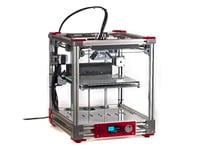
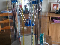
Rostock is a delta robot 3D printer prototype with the following design goals:
Build volume: 8x8x16 inches or 200x200x400 mm
Footprint: 12x14 inches
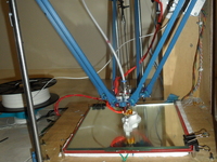
Print surface: 8x8 inches heated glass which never moves
Mass of end effector with two hotends: less than 150g
Positioning speed: 800 mm/s in all 3 directions
Positioning accuracy: at least 30 steps/mm in all 3 directions
Simplicity: fewer than 200 parts (not including washers, nuts and SMD-mounted electronics)
Hardware cost: less than $500 USD
Inspiration: search YouTube for "flexpicker" or "adept quattro".
Closest ancestor: http://www.heliumfrog.net63.net/deltarobot/delta.html
Documentation: http://reprap.org/wiki/Rostock
I'm also uploading Rostock parts as separate things, to make it easier to post specific instructions, comments and derivatives: http://thingiverse.com/tag:rostock
July 17 update: The 3 bottom micro switch endstops are going away in the next release, because the top endstops are already micro-adjustable.
Current release: rostock-2012-06-29.zip fixes a bug in idler_end.stl, motor_end.stl, and joint.stl. All the other STL files are unchanged. Thanks to DigiFab for finding and reporting this issue!
Printing regular G-code with PLA at 50 mm/s for perimeters,
100 mm/s for infill and 500 mm/s for travel moves.
Using Airtripper's direct drive bowden extruder
with MK7 drive gear and NEMA 17 stepper motor,
Teflon PFA tubing (2mm inside, 4mm outside diameter)
and Makergear hotend with 0.5 mm nozzle.
Modified Marlin firmware for realtime delta geometry:
https://github.com/jcrocholl/Marlin
Stepper motors: 4x NEMA 17 (3 positioning, 1 extruder)
Timing belt: 3x GT2 belt (2 mm pitch, 762 teeth)
Filament drive(s): Airtripper's bowden extruder
Ball bearings: 4x 608ZZ, 3x F608ZZ, 1x MR105ZZ
Linear bearings: 6x LM8UU
Smooth rod: 6x 762x8 mm
Plastic parts: printed from PLA on Prusa Mendel
Fasteners: stainless steel, mostly M3 (some M4 and M8)
Hotend: MakerGear 1.75 mm with 0.5 mm nozzle
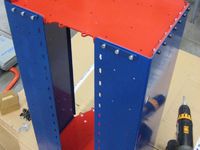
Top and bottom frame: hand-cut plywood (300x350 mm baltic birch)


No results.


i want to make one like this that is 16in x 16in x 32in . it would be awesome but it would take a long time to print im sure. that's ok i still want it. so could i just make this one bigger? would it work to use the same hardware only taller and wider doubling the base and height and triangle arms? why or why not?

i tried cutting the frame with a jigsaw. some of the long straight sides got a little uneven but not where it really matters. how did you cut yours?
Hi Johann. What needs to be done to widen print field and lower the printer? I could use 300x300x200 print field. Thanks.
I have my answer: http://reprap.org/wiki/Rostock_mini or http://www.thingiverse.com/thing:32850
Changable SCAD to change base dimension and height. Be careful though as last lines in frame.scad are rem'ed with *.
You have to configure the size in configuration.scad and then go to rostock_mini.scad and compile.


Hey! Very nice job Johann.
Congratulations.... But i have one question.
Assuming that my construction is correct , the diagonal rods of printer has the same size , and has sufficient size that are configured endstops ... when the hotend does not touch the three sides opposite to these towers delta printer models , namely between ... the X and Y towers , Y and Z and between Z and X. towers what can be the calibration that is not correct ?
My Diagonal Rods has a 317.5mm , but the calibration needs to be with 287.500 for the correct size of calibration cube. Whats happening?

Anyone know exactly how many nuts, bolts and spacers this requires?
Thanks
more or less this:
6 M2x10mm 0,062€ 0,37€
32 M3x10mm 0,053€ 0,64€
28 M3x12mm 0,049€ 1,37€
42 M3x16mm 0,051€ 2,14€
8 M3x30mm 0,073€ 0,58€
70 M3 tuerca 0,007€ 0,46€
4 M3 tuerca autoblocante 0,050€ 0,20€
80 M3 arandelas 0,001€ 0,08€
8 M4x20mm 0,036€ 0,28€
6 M4x25mm 0,041€ 0,24€
6 M4x30mm 0,053€ 0,32€
6 M4x40 mm 0,058€ 0,35€
14 M4 tuerca 0,004€ 0,06€
40 M4 arandelas 0,004€ 0,16€
3 M8x35 mm 0,129€ 0,39€
3 M8 tuerca 0,016€ 0,05€
7 M8 arandelas 0,015€ 0,11€
Tuerca means nut , arandelas means whaser , tuerca autoblocante means locknut, other things are screws. If you bought with
allen head assembly would be easier.
hope it helps.
and 6 x M2x10mm more if you want mount all the endstops :D

Nice printer! If anyone who has made this please check out my guide: http://www.instructables.com/id/Guide-to-Slic3r/ and vote for it in the contest. Thanks!

Hello Johann
I need information about the configuration file configuration.h
I'm trying to configure the Delta Rostock with firmware Repetier on a new electronic card that does not currently support Marlin
There's no particular settings that you must consider?
Or modify only those in the Wiki?
Thank You
greetings
Manuel

always when i try to compaile the firmware, i got an error:
Marlin.ino:42:28: fatal error: LiquidTWI2.h: No such file or directory
compilation terminated.
can anybody help me?
I don't think you are having the same issue I had but when I first researched building my own printer I put the sanguino libraries in my arduino folder and when I tried to upload the new sketches i kept running into compile errors that were never the same error. i removed the sanquino libraries and never have had an issue uploading with the latest editions of marlin and the current arduino software. I don't think you have the same issue but you might want to check there.
Hello
I have problems with the wood panel ...
drawing in dxf there are 6 holes 8mm but according to the project the smooth bars are off the floor so instead of 8 mm should be 3 mm to attach the file motor end ...
sorry but the English are an ignorant Italian :)
thank you
Manuel

I wonder how accuracy is going up along the Z axis.. I have trouble with that on mine and it’s a standard design.
delta 3d printer kit
it is platform is circular
http://www.reprap.cn/he-3d-the-complete-open-source-delta-3d-printer-kit-p-85.html
Hello, I found you from Google, I think you are very talented, And you are also a fan of 3D printer, I am a 3 d printer manufacturer, I would like to cooperate with you, I need the agent, we can give you a good price or commission, if you help us to sell 3 d printers, this is our one of the most popular product at present, would you like to discuss about the cooperation?
Have a nice day
jojo
http://www.reprap.cn/he3di3-prusa-i3-3d-priner-kit-p-92.html
does anyone have a 2d template of the platform? i am wanting to cut it out of wood and need a dimensionaly accurate template

delta 3d printer kit
it is platform is circular
reprap.cn/he-3d-the-complete-open-source-delta-3d-printer-kit-p-85.html

Where is the list of nuts and bolts/washer that I need to buy to build this cool printer!
I cannot find anywhere...
Is this is the right list:
Nuts - m5 1 pcs
Nuts - m3 100 pcs
Self-lock Nuts - m3 50 pcs
Washers - m5 1 pcs
Washers - m3 30 pcs
Cap Screws - m5x20 1 pcs
Cap Screws - m2.5 x 16 3 pcs
Cap Screws - m2.5 x 12 6 pcs
Cap Screws - m3 x 20 6 pcs
Cap Screws - m3 x 35 6 pcs
Cap Screws - m3 x 16 13 pcs
Cap Screws - m3 x 25 15 pcs
Cap Screws - m3 x 6 50 pcs
Cap Screws - m3 x 8 100 pcs
?

you need it? i could buy for you and send, but i think it becomes quite expensive.
tell me if you like, i could buy fro you here
thanks but no :)
I just want the exact list because me and some friends will build this and we will buy all the parts in group, so far I can build this printer including motors and electronics for less then 300$!
But the screws for the platform plate are not described anywhere :)
hello i am having a few troubles with my rostock. I have made a larger model of what is shown above but cannot get it to extrude, connect a geeteck smart display, and level correctly. i have found the problem of the leveling and plan on re cutting my base to change an angle i got off. the display will show the correct setup and settings but the knob will not work to control the display. this is a ramps 1.4 board and it has the sd card on the side of the display, looks like the sainsmart lcd display the extruder is set up for 3mm filament as well as the hose and everything. i have a 3mm j head set up and heats just fine. when i have it all connected and the hose pulls out of the carriage or extruder motor. this is repetitive and will not extrude correctly. i have tried higher tempters and different setups to reduce friction but still cannot find the problem.
This is my electronics kit http://www.geeetech.com/kitsramps14mega2560a4988smart-controllerheatbedhotend-ect-p-700.html
and this is the new hothead i have setup http://www.ebay.com/itm/like/400569524933?lpid=82
this problem i also had , i made a huge rostock ,, 2 meters height , and 500x500x1200 print area ,,
i build the extruder on the head because of friction in the hoze ,
I tryed different types , but the stiff filament + the corners in the hoze , gave huge isue
about the ramps 1.4 you need to take a look in the firmware you can boost power to 255 in the arduino part ,,
then you need to try to adjust the mini pots on the stepper driver to give it more amp ,,
those steppers drivers max is 2 - 2.5 amps ,, this wil not give full power of the stepper to get like 4.5 kg power !
i also had the isue the stepper driver wil reverse when blocked ,, looks like it ,,
i also tryed a geared one , printed one but no beter rsults ,
now i fixed it <extruder straight on the head ! >
if you need some settings i can help !
http://www.youtube.com/watch?v=1_p0vkrSmNE you can mail me if needed [email protected]


Can you measure your distance from rod to rod, on center, between the towers? I'm wanting to model up new base and top pieces for this that I can print and reinforce with readily available materials rather than use large pieces of wood, but need to know what dimensions I should model to. Thanks.

Has anyone gotten one of these to work through a printerboard? I started out with a printrbot with the idea that I could harvest the electronics and print out my own delta

Looks like someone is trying to do this on Kickstarter: http://www.kickstarter.com/projects/shai/deltaprintr-a-simple-affordable-3d-printerhttp://www.kickstarter.com/pro...


Is someon using stepper motors with 400 stepps (1/8 microstepping)? Is the speed enough? How loud are they?
What kind of holding torque do the steppers for the Rostock realistically need? My motors have 55.84 oz-in (4.02 Kg-cm) and they drive the platform around very easily and hold it in place without issue, I'm just curious what the minimum required holding torque is for standard operation. If I know that I can estimate how many additional hotends I can add to the platform without issue.
good call, mine is mostly ABS, but my carriages are PLA, I had to replace them with new ones because they warped from heat in the car two weeks ago during transportation.
Here is a video of mine!
http://www.youtube.com/watch?v=fxGRpHJYAeohttp://www.youtube.com/watch?v...

What is the fastest print speed for this printer, I see that it can travel at over 500 mm/s what are the limitations that are keeping the print speeds down.
I see perimeters at 50, and travel at 500, what are you printing infill at?

I'm also working on a derivative, based on Wolfstock (which is based on Kossel, which is based on Rostock ;)
Anyway, I've completed the frame design and I'm looking at the arms and effector, and I find that I don't quite understand the math. Rather than just scale the design, can anyone point to an explanation on calculation of things like correct effector diameter and rod length? Or am I approaching this in reverse? Do I use as-built values to tell the firmware about my geometry?

@Abcona, agreed that's a nice kit. Andrew (http://3dhacker.com3dhacker.com)

What if i wanto to make a bigger print area? What is the connection between the print area and the lenght of the rods??

Can you explain which bearing are used where in this model? I'm trying to build my own and am confused on the bearings in the BOM.

About Rostock and Sanguinololu 13b (ATamega644b), just two cents.
I got the jcrocholl-Marlin-9d96e51 compiled with
arduino 1.0.1 for Sanguino, with some few changes and avr-size -B
Marlin.cpp.elf shows text=47744 data=412 bss=5886. For arduinos, the
segment bss is SRAM and its above the 4k limit for ATmega644b
When
I look to .bss code ( avr-objdump -x Marlin.cpp.elf | grep bss | sort
> Marlim.cpp.elf.bss), the block_buffer was taking 4928 bytes of
SRAM.
Searching the sources, at compiler time, BLOCK_BUFFER_SIZE is "always" defined as 64 in Configuration_adv.h
So
just force BLOCK_BUFFER_SIZE to 32 to get avr-size -B Marlin.cpp.elf
shows text=47740Â data=412Â bss=3422, just in the 4k limit for
ATMEGA644B cpu.
Or use BLOCK_BUFFER_SIZE as 16 to get avr-size -B
Marlin.cpp.elf shows text=47740Â data=412Â bss=2190, confortable low
water in the 4k limit for ATMEGA644B cpu.
I can't try upload and full test, my sanguinololu 1.3b w/ ATmega644b and all parts for rostock aren't shipped and ready.
Could you check ?
thanks
Alvaro Barcellos

I'm in the process of building a derived Rostock - Rostock_KOM for lack of a better name. It will be the same basic design with a taller (1M rods) and more rigid frame using partial walls on three sides (like Cyclone's) made from 3/4" clear poplar wood and angle aluminum for attachment. The base, top, and print bed are 1" poplar composite plank wood, also very strong. I use a very large 2' x 2' base to keep it stable with the added height. But the big difference is the print bed is floating and suspended from the top by the 1M steel rods yet restrained in place by the walls. If I find the belts need extra tightening I will be able to turnbuckle the print bed down to the base, but only if needed. The electronics will be mounted out of sight under the print bed on the base with a fan to keep them cool. I'm waiting on the plastic parts and the rods to continue my assembly. I'm video recording the process and will post examples and info on YouTube, and then the detail design and BOM here.


Was thinking about his too! Would need a fibre optic laser really though...

What for? This design is all about having the heightened z axis, no?Â
Maybe that's just why I'm excited about it.
Can we use a Printrboard (from Printrbot) and upload your version of Marlin to it? (I'm somewhat of a newbie to 3D Printing)
If not, what type of electronic circuit should we use?

I'm going to attempt this myself. I think it will just require some git merge magic to merge https://github.com/lincomatic/Marlinhttps://github.com/lincomatic/... with https://github.com/jcrocholl/Marlinhttps://github.com/jcrocholl/M... to make a working built. Also you need a modified Arduino IDE http://blog.lincomatic.com/?p=502http://blog.lincomatic.com/?p=...
Ok, that seems a bit too complicated for me. What electronic board is everyone else using then if not the Printrboard? I was thinking of using a Printrboard because I have a printrbot and I am already familiar with it (It's my first 3D printer, so I'm sort of new to all this).
So what other electronic board can I use that requires the least modification?

 Hey shai, RAMPS 1.4 works out of the box so to speak with Johann's stock firmware. Also, if you like RAMPS, we just got the new RAMBo board running our Rostock MAX last night! Thanks in big part to Johann and Johnny from UltiMachine. So those are two more choices for you. The printrboard "may" work, but I'm under the impression it's processor is a bit on the small side? Seems like alot of if's to save ~$50 on a ~$600 machine
I noticed you talk about not needing a heated bed.
As an Ultimaker user who has added a heated bed to his machine, I have some good experience printing both with and without a heated bed. I went without the heated bed for a good six months, and never had adhesion problems. But after pretty much every print, the tape would get damaged. After a whil
e, I got absolutely sick of replacing that damn tape all the time!
When I heard parts just popped off of the heated bed once it cooled, I had to try it. I added a heated bed to my machine, and threw a piece of borosilicate glass on top (no kapton or anything). It was amazing! heat the bed to 55C an
d PLA sticks like glue. Once the print is done, let the bed cool to 35C, and with the slightest push the part just slides off.
Printing with a heated bed has changed my printing experience dramatically. I'm never going back to cold blue tape.
As an advantage, I can also print ABS, and I've found i
t handy to do so for certain parts (being able to smooth out ABS prints with acetone is nice). I used to be a firm believer in PLA, but ABS is nice too. I've currently got about 15lbs of each type!
So anyway, just wanted to share that. Also, I'm printing parts for this now! :)

WAUW!!....A big shout out....All the way from Holland. I am completely new in this area but i recognise ingenuity when i see it!!
The last few days i'm finding out more and more about this medium but i haven't encountered this kind of logical effectiveness
in such a low cost range yet...Untill now that is...ha ha ha ha ha
I would really like to try and build this?.....Everything that a inexperienced nitwit like me needs kan be found on your page?


Well my build is complete. And finally I seems to have it working reasonably well.
Some mods I made were:
Using EiNSTeiN_ heavy duty bowden clamps except I found I had to use Hose clamps to stop the PTFE tube from moving.
Added 3/8 threaded rods in the back corners and near front axis ro allow me to easilly tension the belts
As my rostock is a bit of a shorty height wise, I mounted the Extruder on a bridge under the top to reduce the length of the bowden. for me it is shorter than if extruder is on the side.
The reason I have not cit all the rods to length is that all I need to do is add longer belts and it can grow taller.
:) My blog: http://billdrostock3d.blogspot.com.au/http://billdrostock3d.blogspot...

An interesting upgrade would be to add a tension sprint to the top and bottom of the parallel arms.
Hello together,
is it possible to built the Rostock bigger, as example 500x500 mm workspace?
I am planing to built it with other linear guide and aluarms with Igus.
Thanks :)

You can build it as large as you'd like - you just have to do some math to figure out the new length of the rails, printbed, etc.


I print in PLA and it works great. The parts have withstood a whole filament reel and a half of printing, and we're still going strong.

Hi guys!
How much infill should I use in printing these rostock parts? Thanks!!!
Arnold
Hi Guys, just wanna follow up.. Need to give my friend correct instructions because he's printing the parts for me. :)
Mine was up and running for a while but I had a small issue where the extruder would jam occassionally when it had alot to print. Not long after that the heat resister died. I dont think I seated it properly and it was not disspating heat properly. I didnt have a spare. I am waiting for more to arrive with more heat goo too. In the meantime I made a small mod. I found it difficult to really tighten the belts, you need 4 hands to add tention them and then tighten everything up, so I added threaded rods. Now I can just turn a nut to tighten them.
They ping like a bass guitar now. I also added a twist so the back of the belt goes over the bearings at the top. This definately gives smother travels.
http://billdrostock3d.blogspot.com.au/http://billdrostock3d.blogspot...
My next mod will be to move the extuder. Mine is a slightly shorter rostock so I have my extruder at the top and the length of the bowden tube is about the same as if it was on the side and has to reach the far corner. But because my printer is shorter, I am going to mount the extruder on a bridge suspended inside the printer under the top, a bit above the home position. Being in the middle this shortens the bowden tube by almost 50%. I will try it in the next day or so and report if it improves extrusion/retraction etc.
Same here with the belts. I was printing something this morning and it skipped. I noticed the belts (at least one) was really loose. I happen to have someone nearby to help apply tension as I tightened the screws. The nuts must have worked loose.
Hm, no clue how you got a resistor to die. It might just have detached (desoldered) it's connections?
Tight belts are good - but twisting them usually does put them outside their specifications - wouldn't expect them to last very long that way.
Mounting the extruder smack in the middle of the top end sounds like a smart move - I'll give that a try as well.
The resister is definatley cooked, I would say part of it was not touching the hot end properly. On my other printer it has lasted more than 6 months which is why I was not carrying any spares, I was not expecting the falure.
The belts I am using are only $8.00 and I have spares. I found it removed alot of vibration from the movements, made them smoother. If they start to break I will untwist them.
In regards to mounting the extruder inside, keep in mind my rostock is shorter than the standard so that will give me a shorter bowden. For the standard full height one, the extruder mounted on the side is shortest. Also as mine is a shorty I am able to use the extra rod length at the top to hold my spools.

Got mine build up now, except for the extruder, but I have some issues with the homing sequence. It does home tho the top end stops, but then when it should home to the bottom end stops it doesn't come even close there.
I made a video of the sequence: https://vimeo.com/47376929https://vimeo.com/47376929
Maybe someone has an idea or a hint what I might have done wrong.
Steps should be right, using 16 teeth T2.5 pulley with 80 steps/unit.
Also when lowering Z from pronterface e.g. 50mm an i measure its ok... so don't think the steps are the problem.
there are a couple of settings in the homing code that might affect the behaviour:
DELTA_HOMING_OFFSET - I'm unsure about this one, but it sounds promising...
DELTA_DIAGONAL_ROD - that's the rod length
Sorry I can't be of more help - I run mine without the bottom endstops.
DELTA_HOMING_OFFSET is how far to the side the print head is moved to get to the bottom endstop. This means that from center position, (All carriages touching top endstops) DELTA_HIMING_OFFSET is the distance from a calibration screw on the underside of the platform to its respective endstop location. For a stock Rostock this is I believe off the top of my head 128mm. This means that The head will be moved 128mm toward the vertical bar and then dropped until contact is made with the bottom endstop. Hope that helps :D
How about the calculation of DELTA_RADIUS 175,-33,-18 I guess 175mm radius is the distance from center to the linear rods -33mm
&
amp;18mm = 51mm from linear rods to center of printing head axis?

Same problem! Have made a bigger printer with smaller drive pulleys. Have pinned it down to DEFAULT_AXIS_STEPS_PER_UNIT as the cause of the problem. When this is the original value (40) the movements appears normal, but when adjusted up to 88 (setting for my design) printer exhibits exact same behaviour shown by tkramm. Bit of a showstopper ;) Any ideas on what to look at in the code?
Issue now resolved through speed reduction workaround. Check Google Groups post: "Any known firmware issues with high value for DEFAULT_AXIS_STEPS_PER_UNIT?" [Google groups link is posted after the "Ask questions here" at the top of this page].
This is likely to apply to anyone using DEFAULT_AXIS_STEPS_PER_UNIT value higher than 60.
How do you set the printbed postion then? Top endstops - 400mm? Would you mind sharing your homing code?
that's the basic plan. Right now I don't have a working extruder yet, and the end-stop-adjustments on my carriages are tape and wood sticks that drive me insane ;). Won't get better before it actually starts printing...
I remove the bottom homing, and added
current_position[X_AXIS] = 0.0;
current_position[Y_AXIS] = 0.0;
current_position[Z_AXIS] = 400.0;
at the end of G28.
It's not perfect though - either I have only 300mm travel, or am doing something stupid otherwise, and depending on the DEL
TA_ZERO_OFFSET, it also make a superfluous move when issuing the first move after homing (guess I need to add that to the z position or such).
I'll publish it soon as it's working.

Awesome design. This design and files print very well and easilly assemble with nearly no clean up. One only needs to drill out the 8mm for the bearings.
Question: Do you think, after your use, that the six bolts on the lower motor mounts which clamp to the steel rods would work fine with only four bolts, evenly distributed? That is - use two bolts on the motor mounts for each rod? The rods do not get much pull/push and the plastic holds quite tigh
t. Just a thought to lessen fasteners and keep the solid integrity of design.
PLA - ABS... To those that ask. Note that ABS is the plastic most all the other printed printers were and are printed from. So, if you wish to - print ABS. I think this is the first published printer mostly from PLA. Plea
se correct me if there was another. I do not have experience with PLA but, it sure seems to work well for Johann.
On the small u-joint parts. They can be printed without raft and no fan. Also, no blowing - ;). For my prints I did not use any raft or supports. But, I was not able to print the rods
because my Thing-O-Matics build platform is too small. I am using carbon kite rods. Looks very High Tech and cool still.

Have a look at my half-rod design (http://www.thingiverse.com/thing:33673 )

my wooden repstrap version has no clamps at that position - just undersized holes, and that seems to work just fine. I mean it's not like you can pull the rod up on the LM8UUs...
Hi Guys,
So I'm ordering wood for this project.. Will MDF work? Or will the heat warp it in time? :)
Hey guys, has anyone had trouble with the Airtripper Bowden Extruder skipping? :)

If you want a reliable extruder use greg's hinged extruder ...
I tried a lo of extruders and greg's seems to be the best one out there ...
Does anyone have a idea when a kit wil be avialible?
maybe i can be reseller for the netherlands i would like to do that ;)
i would like to make a prototype to but it isnt realy affordable to do that becaus the shipments tho the netherlands by the various shops
i cant wait :-D
Greats from the netherlands
there are a lot of suppliers and materials right here in NL ... no need for high shipping prices .. lol
kom jij ook uit nl dan ?
waar heb jij het allemaal besteld dan ?
Ik bestel alles bij een vriend van me...
als je goedkope spullen zoekt stuur ff een PM...
kan alles regelen tot nozzles( hotends) aan toe ..
:)
There is a dutch shop that delivers virtually everything but the rods (ebay), wood, screws (local hardware store), the power supply (ebay) and the slightly more 'exotic' ball bearings (ebay again).
They're located in Den Haag - you should be able to google the (don't know the thingiverse policy on mentioning suppliers)
Didn't pay more than 25 eur in shipping for mine (to germany) :)
hello to all I have a big problem with the sanguino because I use a atmega644 sanguino but the program is for a arduino mega my question is how to charge to sanguino and wath is the modified program. :'(
&
amp;gt;:o
Most likely, all you need to do is switch to the correct mainboard in the configuration.h. There is some additional detail for sanguino in the Marlin Readme that seems to require you to copy some files around...

Oh, and those using carbon fiber rods and the jaws.stl...what are the lengths of the carbon fiber tubing you are using?
I think I cut mine to 235mm to make 250mm rods. Just off the top of my head. The general idea is that as long as all of your rods are identical length then you can change the firmware to match your rod length, which entered as a mm measurement from hole center to hole center on each jaw end. In any case - You probably want Pultruded Carbon Tubes: Part Number: 020961; Pultruded Carbon Tubing: Description O.D.": .1880";Length: 60";I.D.": 0.116";http://O.D.mmO.D.mm: 4.78mm;Wt./gm: 25.2 gm. I ordered this from http://www.goodwinds.comwww.goodwinds.com in one 60" length which gave enough for 6 rods plus some offcut. Price is good but shipping kills it.
Anyone here make a hexagon cutout for the base? Happen to have it in a dxf format?
Try this link... I had mine cut during http://Ponoko.comPonoko.com's large format sale. http://www.ponoko.com/design-documents/get-eps/305864?target=_blankhttp://www.ponoko.com/design-d... - its in EPS though.
Hi Johann,
I still have one question, that is what about the rod lengths, because with the same rod length the platform hangs at the front?
is it ok to adjust the front and rear ones?
front a bit shorter like 2-3 mm and back longer by 2-3 mm..
Just wanted to let you know that my son and I got our Rostock up and running last night. We are still waiting on the arrival of the 6 linear bearings in order for us to finish up, but we did manage to get it moving just to test it. Video Proof! - http://youtu.be/jXXPKiYkMsEhttp://youtu.be/jXXPKiYkMsE . FYI: Top and Base are Polycabonate, side is one piece bent aluminum. Filament spool reel is built into the back side with spare flange bearings. Arms are carbon fiber kit rod. - I'll be adding more images to my gallery over time - https://plus.google.com/photos/110997713826931701065/albums/5773609700932594497https://plus.google.com/photos...
Did you drill out the min end stop bolt holes? Every photo I see looks like an M4 but the part I printed only had M3 sized holes where they go.
RISL, the arduino software version which works with the Marlin firmware is arduino-1.0. The code I compiled is Johann's version of Marlin, available for download as a ZIP file from GitHub - link is provided above... but here: https://github.com/jcrocholl/Marlinhttps://github.com/jcrocholl/M...
Almost there.
Its all built and printing.. kind of. Retractions dont work, I have tried various settings but extruder seems to just stop rather than retract and then races forward adding more plastic. As a result there are blobs everywhere and way to much plastic. But its running at least. As I have excess rod length at the top I have added a bar to stop my filiament spools there. Will eventially add one to all 3 so I can keep my favourite colours up there. Pictures on my blog. http://billdrostock3d.blogspot.com.au/http://billdrostock3d.blogspot...
Awesome - like the color as well.
Random idea: it might be a cold soldering joint on the direction pin - that way the extruder wouldn't be able to reverse.
Hi tprime,
Nope it turned out to be user error. I had tried to fix the "cannot extrude" issue earlier on myself before the post was made that showed which bit of code to remove. I got it working and later when fiddling around I muct have sent the wrong firmware down.. I have deleted the bogus one now so that cant happen again. DONT_KNOW

Hi All,
Has anyone found a way to attach a RepRapPro style hot-end to this platform yet?
If not, I guess I will have to make my own way forward ;)
Hi Everyone, perhaps you could help me out. What size holes should I put on the plyboard? I'm currently making a layout for laser cutting plyboard (or maybe acrylic, havent decided yet).
Anyway, looking at the jig's stl it says its 4.4mm in diameter. I think that's too loose for the M4 bolts. Should I reduce my file to fit exactly 4mm? or just keep it at 4.4?
Thanks! :)
If either of ya'll have made laser cutter files for this project, id be super interested in those. Please, and Thanks!
I used 4mm holes if that helps. M4 through the wood and into the plastic parts
I have mine moving and homing and drawing with a pen. I could use some help getting the extruded working. Not extruding cold or hot manually (I read there is a bug that won't allow extruding unless movement). Also need to know steps per mm for the Mk7 modified boweden I tried 50.xx from MakerBot firmware. Stripping and not laying down enough. Also, does the tube go all the way down into the hotend part? It doesn't want to feed in well because the filament has to align just right otherwise.
Well I have confirmed that the problem with my extruder seems to be in the firmware. If I load older firmeware the extruder works fine but in the version for the rostock. Nothing happens. I have been through all the settings and cant see why Extruder 0 never moves.
You'll have to change line 1387 and following in Marlin.pde
It reads
if ( cartesian_mm
&
lt; 0.000001 ) {
return;}
which prevents any (extruder) movement without xyz movement.
Just remove these tree lines and reupload.
I just got my Ramps 1.4 yesterday, completed the wiring, hooked everything up on a dry run and noticed the extruder stepper not working. But As TechnoBill noted, the stock Marlin firmware runs the extruder so I was just getting ready to delve into the code... I was going to look into the cold_extrusion prevent code thinking it would be there. So to TPRIME; THANK YOU! For making my life easier 8-)
Aha! I have come here because if the same problem. I cant extrude. Everything else is working. :-(

If you need someone to make the parts for you, there is a Company called
Matterhackers that will print them for you. Don't forget to order the jig and other external parts that you may need before asking for the quote. They will need the Thingiverse page and stl name. Email [email protected]
to get a quote.
When do you think the next version is ready?
I really want to start building the Rostock! :)
I'm thinking about using the Makerslide so I can make the machine more rigid. :)
It's moving! I've commented out the bottom homing code (Johan, how's your change coming along?), but afterwards all it does is move downwards with all three carriages. I can change the speed by going different lengths, but it never stops moving.
Does anybody have any ideas what could be wrong?
Should probably mention that I have the same behavior if I keep the bottom endswitches in there and press them by hand (cables are to short for mounting right now...)

Hey I think that one could actually print higher than the rods with very few tweeks.
The idea would be to flip the delta upside down at around mid print. That could probably be done in software by raising the 3 carriages up to the roof, then, one at a time, lowering each carriage way lower than the end effector.
Of course the roof would have to be openned and the arms whould pro
bably have to be curved in order to provide clearance around the print.
Good luck on your project!
Great project! I'm on my way to building my own. I've printed all the parts and they look great.
I have a question about the smooth rod. If the belts are 762 pitch, isn't a 762 long smooth rod just short of the motor and idler ends? I'd assume they would only go halfway into the clamps.
Cheers,
Fred
Correct.
The longest theoretical belt that will fit is 744 tooth + or - a few teeth due to pulley diameter and top idler diameter.
Buying belts by the foot is twice the price of closed belts, and nearest closed and available length is 762 tooth, which can then be cut to length. I think that is where the 762 tooth belt in the BOM comes from.
Reprap forum hasn't emailed my confirmation so I am asking this here.
How have the users been mounting the heat bed? Element side up (side with led and wire pads)? It seems like this would transfer the heat better and not directly heat the wood. The glass can be offset from the front so it would protect the led's. Has anyone used insulation such as cork between the heatbed and the wood base or have they been all mounting directly?

There's a section on the reprap wiki about using both sides of the heated bed. http://reprap.org/wiki/PCB_Heatbedhttp://reprap.org/wiki/PCB_Hea...
Just about any mounting method works, I currently have mine element down on cork with glass on top.

Hello all. I'm new to 3D printing. I was about to start building a MendelMax when I stumbled on the Rostock.
I'm an Electrical Engineer of 29 years, specializing in embedded systems hardware and software, so building a 3D printer is pretty cool. I should be able to help with various firmware improvements, once I get something built.
I'm excited about building a Rostock prototype and helping to improve it, but I don't have any way to print the plastic parts.
Can anyone suggest a source who would be willing to print the latest design of the parts. I'd obviously pay for your time and materials.
Thanks...greg
I'm also interested in getting the printed parts! If anyone in Europe could print them for me, PM me please!

Honestly, with the experimental nature of this. If you want to print and print reliably, just make your MendelMax. While this will be a cheaper machine in the long run, I think it would be a nightmare for a first time builder considering there are going to be issues. I have made a Rostock already and am having issues getting it going right now and I've been doing this for years. The firmware is buggy and there isn't a huge team of people that all know Rostock willing to help. If you wait a few months that may change. If you want to build a printer now though, then do a tried and true design. You will have a much more enjoyable time.
If you're like me and don't care about the challenge then there are likely people on this site, including myself, that would be more than happy to help get you parts. They wouldn't cost all that much to print and would take only a few days.
What's more enjoyable is of course debatable - like gyurko, I like the challenge. I'm even trying to repstrap a Rostock (and if the stepper drivers would finally arrive, it would already be oozing plastic. Probably all over the place, though).
afpiper: would you elaborate on the firmware being buggy? I have hacked grbl in the past and might be able to throw in a few lines of code O:-)
ok, I found a first bug - the firmware can not extrude without head movement.
I"m all about the challenge. I think I'm building one for the sake of getting it working. A tried and true design takes out most of the fun.
Let me know what you want and I'll pay you however (check, paypal, etc.)

I've been looking into this option. The lincomatic fork of the marlin firmware does support Pintrboard. Johanns delta code needs to be added in the correct locations and this option should work just fine. I was going to buy Printrboard (around $130) and attempt it even though I've never worked with Arduino hardware, but i found that MakerGear carries assembled ramps 1.4 with sd card and 4 pololus for $150. So i went with easy. 8-)
It would be cool if someone setup a Google Group for others building a Rostock. ;)

It would be cool if someone setup a Google Group for others building a Rostock. ;)

I'm idling in #rostock on http://irc.freenode.netirc.freenode.net, though there isn't anyone else here :)
I'm an sgraber too, but we're not related. What are the odds two sgrabers are building Rostocks?
Well, there is the 'Delta robot's sub section of the reprap forums: http://forums.reprap.org/list.php?178http://forums.reprap.org/list....

The BOM is missing the quantity of penholder and jaws parts needed, is it just 1?
The penholder.scad is only needed if you want to attach a pen or dial indicator. For the bowden tube attachment, use bowden_hotend.scad instead.
You need either 6 printed rods or 12 jaws (for use with carbon fiber tubes from the kite shop).
Thanks!
Would you mind uploading a STL of bowden_hotend?
Uploaded http://www.thingiverse.com/thing:27840http://www.thingiverse.com/thi... for you. :)

This is my first time compiling Marlin code. I will be using the Mega 2560 and the Ramps v1.4 board. I am also getting the "Reprap Ramps 1.4 smart LCD controller inclunding smart adapter" which includes an SD card interface. What MOTHERBOARD setting do I use? I set to 33 and enabled the ULTIPANEL / NEWPANEL and SDSUPPORT but I am getting an SDCARDDETECT not defined during compile. Also when I looked at the pins.h there are these options but doesn't mention 1.4: // uncomment one of the following lines for RAMPS v1.3 or v1.0, comment both for v1.2 or 1.1
// #define RAMPS_V_1_3
// #define RAMPS_V_1_0
Found the LCD info. Just need to confirm settings for Ramps 1.4 in the pins.h file.
Hi Johan,
I was looking wich motor goes on wich connection, but can't find it.
can you tell me please?
X: front left motor and endstops (electronics side).
Y: front right motor and endstops (plywood frame side).
Z: back middle motor and endstops.
http://reprap.org/wiki/Rostock#Assemblyhttp://reprap.org/wiki/Rostock...
thanx, im soldering the last endstop now.
After this it will be my first powered test .. 8-)
Johann, does the print circle for yours encompass the entire printbed, or are the corners left unused?

It looks like the corners are unused - the actual print area is about a 9-ish inch circle.
Hello Johann!
I absolutely love the inspiration you have caused in the community for delta bots! I built a small delta that was 2 dof x/y for plotting back in high school with erector set but never finished the firmware for it.
I am very interested in perhaps getting a little bit of help from you in building
a micro stock. I have a frame already built and if you could help me figure out some geometry I would truly appreciate it. First off let me show you the frame here
&
gt;
&
gt;
http://brainspl.at/microstock-framed/index.htmlhttp://brainspl.at/microstock-...
http://brainspl.at/microstock-frame/index.htmlhttp://brainspl.at/microstock-...
I am using a G10 CNC'd tricopter frame design of mine for the top and bottom frame parts and I am using http://microrax.commicrorax.com 400mm tall 10mm tslot extrusions for the uprights and will use 300mm long PTFE slid
ers for the linear motion. I also have some very aggressive 5 start lead screws I will use instead of belts. I have a heated build platform which is 120mm x 120mm.
Here are a few little pics of the ptfe slides and the leads crews I want to use on the towers
&
gt;
&
gt;
http://brainspl.at/microstock-measurements/index.htmlhttp://brainspl.at/microstock-...
http://brainspl.at/micro-stock-leadscrews/index.htmlhttp://brainspl.at/micro-stock...
Could you possibly lend me a hand in sizing the center carriage and the arm lengths? with 400mm tall towers and 300mm sliders should I mount the sliders all the way butted up to the top lea
ving 100mm under the slides for the arms to move on? And how large should the center carriage and arms be?
I am wiling to do the work and release all this design back open source if you can help me get a better understanding of how to size this little guy. If you like it I will even CNC a few of th
ese top and bottom frame parts for you and send you some 10mm microrx slot to build your own in trade for info on how to properly size this.
I can CAD model the arms and everything myself if you can help me with the size of the carriage, the lengths of the arms, how far apart the parallel sets of a
rms should be etc. I have 6mmm and 4mm square carbon fiber tubing with round ID hole for the arms and I have UV joints, Clevis's as well as rod ends and a few other nice hinges I can use on this little guys as well as a CNC milled center carriage for the extruder mount that will be super lightweig
ht allowing for a slightly heavier extruder perhaps.
Any help you can throw my way would be greatly appreciated. And if you can hep me properly size this microtock I will happily send you a set of parts to build this frame for yourself.
The radius of the frame is 110mm. So 110mm from the center of
the frame to the center of one of the 10mm slot uprights.
Thanks in advanced for any help with this.
I now have mine built. I am finding no instructions on how to wire it up. I have guessed and it seems to work (kind of) I assume min endstop is at top? If in Pronterface I home Z it goes to top. Moving manually in X Y and Z seems to work correctly most times. But I I try to print anything, it goes crazy does not seem to do the nice dance that you see in the vids where it goes down to the max stops, etc. Are there any pages that show this next step of wiring and basic testing and calibration?
Thanks Johann,
I am at that next stage now where I am fine tuning the alignment etc. I am finding that it is not moving quite level with the plate. For eample moving in Y the as it moves back it lifts the back of the carriage by a mm and as I move it forward it eventually levels out. I am not sure wether to adjust the Top stops or the bottom ones to get it aligned correctly and travelling flat. When you have nothing to do, maybe you could add a fine tuning guide. With this design it can be difficult for those of us that are mechanically challenged to understand what to adjust to remedy these fine tuning issues.
I'm continuing to improve the http://reprap.org/wiki/Rostock#Calibrationhttp://reprap.org/wiki/Rostock... wiki. Please let me know if it works for you, or if you have more questions. :)
I am almost there. I am having a little trouble getting it perfectly level with the plate.. there appears to be a slight variance as it moves aroud. But its close. I did a 2D test and posted a video. It can be accessed through my build blog.
http://billdrostock3d.blogspot.com.au/http://billdrostock3d.blogspot...
Noticed some discrepancies in the rod files. Is it supposed to be 250mm long or 260mm long?
The rods are 250mm universal joint center hole to center hole. 260mm overall. The STL's are correct.

I couldn't get the rod.stl, which has some errors, to slice properly with Slic3r. So I tried generating it from the source, but the source configuration.scad lists the rod length at 120, which is clearly incorrect. But given the rod ends add some length, I wasn't sure if the correct value for the config file was 240 or 250. Or something else entirerly. Can anyone state for certain the overall length of the rods with the ends, and the correct value for the configuration.scad file?
250 mm is the correct center-to-center distance of the holes for the U joints. The total length of the rods is 260 mm. It's okay if your rods have a different length, you can adjust DELTA_DIAGONAL_ROD in Marlin.pde in the firmware. Just make sure the 6 rods are all the same length.
Hello Im new to 3d prnter. Compare to other 3d printers..is this more expensive to make or cheaper? Thanks

do you have a list of the parts to be printed? (how many of each stl?) for some reason I can't find it :P

There is a BOM in the reprap wiki linked above, and an Google Docs link in Johanns comment waaaay down.
Here you go 8-)
https://docs.google.com/spreadsheet/ccc?key=0AihVdu60WUfgdG9PY3B1Tk1GaVA4TTA1djRDT0xkLXchttps://docs.google.com/spread...
Yeah i like it i hope there will be a kit soon or maybe i can be beta tester ?
greats form the Netherlands
Before I ask my question, i simply MUST say that this is a simply amazing design !
Well, I was wondering: if I wanted to scale the x and y axis of the build platform to say 300x300 mm, how long do the diagonal rods have to be ?
How are you allowing for wear in the joints? As there are no bearings in the printed system do the threads form the screws cut into the printed parts?
Yes, the holes should be pretty tight, and the M3 screw threads should cut into the universal joint pieces. Initially they will have some friction but soon they will run smoothly and without backlash. If you make the holes large enough to spin freely from the start, you will have backlash problems later.
I'm building mine at the moment and I am very excited about it. Thank you Johann for putting this together in a simple to understand and build package! 8-) I'll be posting my photos soon.
Johann, I would like to incorporate your Marlin firmware improvements into the Marlin/lincomatic fork. This will allow use of the Printrboard instead of Arduino/RAMPS1.4. Printrboard is an inexpensive ($130) board with integrated steppers based on Atmel AT90USB1286. Saves a bit of money. Have you
considered merging your code? I might be able to do this myself, but not sure on my capabilities since I am a beginner.
Regarding the rods; for comparison purpose I first printed a full rod in PLA and made a second one with the end_jaws.stl and a hollow carbon fiber kite rod tube. The PLA printed r
od weight is 13.7 grams each vs carbon fiber 3-piece rod at 7.4 grams each. That's 37.8 grams less weight for the 6 rods. The CF rods are also much stiffer than the PLA version.
The hollow CF pultred rod is available from http://goodwinds.comgoodwinds.com 60" x .188", part #020961 and is $7.79. This provides enough
for all 6 rods.
Thanks again, this machine is fantastic!

Do please post a derivative if you do get a code for the printrboard.
I am making a traditional printer
(ultimaker gantry/bowden derivative) using the
printrboard for my electronics,
i would love to also build this design
if i could move the electronics over
(and eventually buy a second board)
Carbon fiber sounds like a great mod. less mass to move
and stiffer!
Just curious why a belt drive is used instead of a screw like on a desktop CnC? I would think that would be more accurate.
Just watched the bottle video I can see how fast this is on the moves between print areas. I can see why belts are used now instead of a screw.

I'm a little confused DONT_KNOW with the wood pieces.
I see two different designs, and can not find the measures of the poliwood in the sides.
(appears that the hexagonal design takes more space)
could someone clarify the dimensions of the pieces of wood?
Sorry for my poor english.... :-[
Great job! :)
http://www.thingiverse.com/thing:25000http://www.thingiverse.com/thi... includes up-to-date instructions for the top/bottom plywood pieces. The hexagonal base was a very early experimental version, but it was too small for the 8x8 inch heated bed. The current base is made from 300x350 mm plywood rectangles.

Repstrapping this I of course messed up one of the edges
&
amp;gt;:o.
Hint: The front has to be asymetric...
I believe I've fixed it by extending one of the carriages into a triangle (shapelock to the rescue), but a simple SVG of the shape in addition to the (probably very useful, if I could print it) rig would be nice :-P.
http://www.thingiverse.com/thing:27573http://www.thingiverse.com/thi... is just that!
Ah, I wish and thingiverse provides. Retroactively ;). Awesome.

looking even more closely, I think I've simply reversed the angles and the front actually is symetric.

This is seriously a cool design. I'm building one as soon as I'm back in the workshop.
This is a fantastic AMF printer! :-D
I noticed in Marlin you are using the Ultimaker PID settings for you MakerGear Hotend. Are you getting reliable temps? I had to change this setting with my J-Head Mk V-B via M303
I'm using Ultimaker PID settings with a MakerGear hotend and getting ~0.75 degree swing.
Actually I disabled PID temp because I couldn't find the right settings for the MakerGear hotend. Will try PID again later.
On average how much watts does the 3-D printer consume? For example how much did it consume (roughly) to print the owl model that is shown in the video
I don't know about this exact one, but typically this type of printer needs a 250W 12V power supply.
Is it possible to mount a cooling fan on the print head carriage, or is this not required any more even when printing PLA?
It is possible but I was trying to reduce the weight of the moving parts. So I'm using a large oscillating desk fan sitting next to the printer. You can see the fan in this picture: http://thingiverse.com/image:150904http://thingiverse.com/image:1...
No. The print head weighs less than 50 grams, and the three stepper motors have significant holding torque even when they are turned off (permanent magnets). You can move the print head around with your hand when the motors are turned off, but it's not very easy, and it will stay where you put it.
I built one, and its moving ;-)
now wondering how to calibrate axis_steps_per_unit, since X/Y/Z motion is not linearly connected to print head motion ?
(using T5 Pulleys with 8 teeth)
thanks for the good work
You don't need to "move and measure" if you know the pitch and number of teeth on your pulleys. Simply enter your pulley size on http://calculator.josefprusa.cz/#MotorStuffSPMBhttp://calculator.josefprusa.c... and it will do the math and show you the result (80 steps per mm in your case I think). The firmware takes care of all the non-linear math so you don't have to include that in this number. If you do want to "move and measure", use Z movement, because X and Y are non-linear.
Now I don't understand. Didn't the firmware take care of all the non-linear math? Can't you move and measure och X and Y then? Yes, you should need to do it a couple of times. (because of the non-linearity). But then it should stabilize.
I have found the calculator good to begin with. But I always move and measure to get the last precision that I need.
The steps per mm for X and Y is not constant across the print area. In the middle it is around 30 steps per mm, and near the edge it's more than 300 steps per mm because the push rods will be nearly horizontal. You need to tell the firmware only the steps per mm of each timing belt, and you can get that number by measuring Z movements only.
Since you adjust the parameter with a percent error, it should work with either axis At least as long as the rest of the parameters are right (for the non-linear math). (You don't measure step/mm, you measure error between ordering a certain movement in mm and the result in mm and adjust step/mm in percent from the error)
But you are probably right that its easiest to measure step/mm in z-axis because then its not dependent on all other parameters (length of arms for example) being right. After that you can probably measure and adjust the other parameters to get a consistent result all over the x,y plane.
How good
has you got the x-y plane? Do you have problem at the sides? Have you tested to print some big calibration objects?
Does the firmware compensate the step rate so that constant speeds can be obtained anywhere in the XY plane?
Should be exactly as before. Give an order of movement, measure the movement, adjust the parameter accordingly.

I have a feeling I'll end up making one of these in the near future, lol. :-D
You've got 1 pack of 10 608zz and 1 pack of 10 flanged bearings in the BOM.
How many bearings are actually used?
3x 608ZZ and 3x F608ZZ (F = flanged) for the timing belt idlers at the top. If you can't find flanged bearings, you can try using normal 608ZZ with a printed plastic flange. If you want to use smaller timing belt pulleys on the motors (which might be a good idea) you could also replace 608 (8x22x7 mm) with 688 (8x16x6 mm) or similar.
Also 1x 608ZZ and 1x MR105ZZ for Airtripper's direct drive bowden extruder.
Wow look at all the Likers!
I'm building ---- Well I made my 12" (~300mm) rods longer to 17.9" (455mm). I then calculated a loss of useable rod at ~4" (~101mm) for base and end-stops. Then using a ratio of 16" printing to 30" height from your Rostock printer I calculated for my build [(16/30)*13.9] a print height of ~ 7.4" (
~188mm). This will printer will have 473+ cubic inches of printing area! This man's Rostock will be 8" (~200mm) X 8" (~200mm) X 7.4" (~188 mm). How many cubic mm?
Ordered are: motors and linear bearings. Stepper drivers are in a box waiting. Next is to decide on the hot end (buy or build or design
&
amp; build?) and which electronics. I've even got the LED lighting circuit nearly ready. Where will I cut my base? Will the plywood be swapped for acrylic instead? Ah, the fun of building. Excitement is in the build...... :-D Thanks again, Johann!

Wow. And I thought my Mendel was fun to watch. I think my Mendel electronics will be reborn as a Rostock.

This looks awesome! I'm feeling another build coming on.
How do you pronounce "rostock"? roe-stock, raw-stock, roz-talk?
I say Ross-tock but your other pronunciations are fine too.

This bot looks like something Dark Elves would make.
I'd enjoy watching it move even if it wasn't printing anything.
Amazing design. I am working up a design based directly on this, using most of the same mechanical design but modified to use Makerslide and V-groove bearings instead of smooth rod and linear bearings. That's mostly because I found a pile of small V-groove bearings cheap at a junkyard, but the Makerslide does have the advantage of being more rigid and has a hollow channel inside which can be used for routing wiring. One question - would you recommend 0.9 degree per step or 1.8 degree per step motors for use with this design?
For the stepper motors, use whatever you have in your workshop. If you are buying new motors, I think 1.8 degree per step (200 full steps per rotation) is more common for RepRap printers these days. Modern electronics (e.g. the RAMPS 1.4 which I currently use) support 16x micro stepping, so there are 3200 micro steps per rotation which is plenty.
I suspect that the electronic connections are the same as for any RAMPS-based 3D printer. The only difference should be that there are 6 mechanical endstops instead of 3, and the X/Y/Z motor connections are going to the three drive motors in the base instead.
Yes, it's the same wiring as Prusa Mendel for example. I'm also beginning to think that the bottom endstops are really unnecessary because the top enstops are already micro-adjustable. So you can skip the bottom endstops if you want, and we can simplify the firmware to ignore them. I wired my endstops "normally connected" so the circuit is interrupted when the endstop is hit. But that's easy to change in the firmware configuration.
The prints look fantastic, amazing job!
How is the dimensional accuracy as it stands?
I am having trouble finding the right information. I have all the parts and want to start making the top and bottom boards and mounting everything but I have conflicting size information on the various related Items. The the Idler end for rostock says to install the idlers on a plywood circle of 150mm radius but the PDF template elwhere had dimentions like 167mm. I am not sure which is correct or does the width not mater that much as long as they are exactly 120 deg
Sorry for the confusion, 167 mm is correct. See RostockBaseDims.pdf by Modpod http://thingiverse.com/thing:24973http://thingiverse.com/thing:2... or print the drill jig http://thingiverse.com/thing:25000http://thingiverse.com/thing:2... to make accurate plywood parts. The 150 mm radius was used in an earlier version but it was too small for a 8x8 inch heated bed. I have updated the instructions on the idler end page.


Thanks for confirming. Being able to use the jig does make things alot easier.
I expect you are being ohassled by a lot of us imptient early adopters that are getting involved before all this is really bedded down. But its such an exciting design. The Lava Lamp of 3D printers.. I just cant stop wathing it print :-)

Can it print to the full circle? i.e. you mention a 8x8 heated bed, so can it print a 11.31" dimeter circle?
The current prototype can't really print the full 8x8 heated bed. It's closer to a 9 inch circle. But yes you can print a vase with overhang that is wider than the print surface.

Sorry, not yet. This is really still a prototype. I'm pretty sure that the first beta testers are going to find several problems and make improvements. Some folks are already planning to replace the plywood frame with OpenBeam and the smooth rod with OpenRail, which sounds pretty exciting. Stay tuned!
I am in the process of building one of these. A couple of notes:
The specified GT2 belt of 762 teeth is longer than the theoretical maximum of 744 teeth that can be used with a 762mm / 30inch shaft (15mm idler and 15 tooth drive pulley). Long belts are only available by special order, and need to be slit from a wider belt. Best to use open ended belting instead
.
Currently redesigning the universal joints to use .75" PTFE or Delrin balls, and aluminum rod to reduce slop and wear inherent in moving a rough grooved part (screw) against a soft plastic part (PLA joint). I will post STL files when I have finalized the design.
Is the link above for Firmware: https://github.com/jcrocholl/Marlinhttps://github.com/jcrocholl/M... the actual firmware you are using? Or do you have a more customized firmware?
I've got my parts printed and some vitamins on order. I need to finalyze what electronics I'm going to build and the motors to run. Pretty excited.....
Yes, https://github.com/jcrocholl/Marlinhttps://github.com/jcrocholl/M... contains all the changes that I made to the Marlin firmware, and http://forums.reprap.org/read.php?147,138588http://forums.reprap.org/read.... explains some of the details. It's a pretty hacky proof of concept, and I hope we will have better delta firmware at some point.
Very nice. It looks like you are using the plastic as a bearing. Do you have any repeatability or backlash problems with that? Also, do you have an idea how it will wear across time? Great work - keep us posted with new videos.
Did you mean linear bearings printed from PLA? I experimented with that for a while but LM8UU steel ball bearings seem to work much better.
Or did you mean the universal joints (PLA with stainless steel M3 screws) at both ends of the diagonal rods? In an earlier version some of these screws unscrewed themselves after a while, but I think that is completely solved by the inside counter nuts. My prototype has only printed about 1 kg of
PLA, but so far there is no sign of wear and very little backlash.
It was the latter case. That just seemed like a high-wear spot in the design.
Just ordered parts for the build, but I notice that you have what look like longer than "standard" LM8UU bearings on some of the rods. Is that necessary or what you had on hand?
DigiFab is right, the longer LML8UU was just an experiment to see if it would keep the carriage more horizontal. It doesn't seem to make a difference, except for added cost and weight.
This has really come along nicely! Looks like you're getting good print quality too. Good job! :-D
How low do the carriages need to slide on the rods during the printing/operation? I've some short rods (300mm) and am thinking of extending them up several inches (75mm) from the base. DONT_KNOW
The diagonal suspension rods are 250 mm long so the max required carriage travel for printing the first layer is somewhere around 200 mm (they go from vertical to almost horizontal). You need to add the build height to the first layer travel: 200 mm + 200 mm = 400 mm carriage travel required if you want to print objects up to 200 mm tall. If you really want to use those 300 mm rods, it could be awesome to try building a mini-Rostock with 100x100x100 mm build volume. All the parts would be the same, only the diagonal rod should be reduced from 250 mm to 125 mm maybe. You can still buy longer smooth rod later and upgrade to a bigger build volume.
Using the math ratio of your machine - 30"/16" to get the rod lengths required for my desired minimum 6" height, I need to have 11.25" rods. So, I have decided to put extensions on the bottoms of my rods of approximately 76mm to get my rods to about 286mm. Thanks for the mini idea but, although I liked it too, my sons would like a larger print area than our current MakerBot Thing-O-Matics. What I'm now working on is a 200mm X 200mm X ?150mm print envelope. ---- I want to show off your machine working next to my other Delta. Too Cool!!!!

SWEET!!! Just noticed this thing was up and printing today. You have come a long way in 5 short months. Awesome Job! Fast, precise, and it looks good too!
:-P Well count me in too hehe... been printing the parts on my slow old printer all day.
This looks awesome.
12 joints. No jaws if you are printing the rods on an 8" x 8" bed. If you can't print something that big then use carbon or other tubing. You then will need to print 12 jaw ends to make 6 rods.
I can't print the rods on my Thing-O-Matic but, happen to have carbon kite tubes. You could go get metal hobby tubing also.


Hmmmm.... am I missing something???
On the printed parts in the rostock-2012-06-29.zip how many of each part to be printed? Some are obvious but how many joints and jaws do I need to print for 1 on these printers?
Ok I couldn't resist making this thing after I saw how nice you got it working. Amazing job man, props!
Of course I couldn't just color within the lines and I happen to have these nice 900mm long CCM belt driven rails that can move at 1200mm/sec... so I am building my rostock, lock stock and smoking barrels like this
&
gt;
&
gt;
I'll post more p[ics here or on a "I made one" page this coming week when I finish. Can't wait to get this working, thank you for the design and opens cad too, rock!
I've made further progress on this 'fork' of the rostock and hope to have it printing within a week or two, Here are my CAD models(well screenshots) showing what it will look like more or less
&
gt;
&
gt;
http://brainspl.at/TrinityLabs-Prostock-DeltaBot-3dPrinter/index.htmlhttp://brainspl.at/TrinityLabs...
Where did you find these? I've exhausted every keyword I could think of to search for them.
It took me a long time to get to the source of these belt rails. And I finally negotiated a 2 year exclusive USA reseller right to these rails.
So I will have them in stock in my web store in about 3 weeks when I get a large quantity of them at http://trinitylabs.comtrinitylabs.com
Awesome work, Johann! Just about done with printing all the parts.
What length are the belt loops?
Hoping to help you out with some documentation as I build too.
My prototype currently uses 762 mm smooth rods and GT2 timing belt with 2 mm pitch and 762 grooves:
https://sdp-si.com/eStore/PartDetail.asp?PartID=75955https://sdp-si.com/eStore/Part...
&
amp;GroupID=342
This gives me 8x8x16 inches (20x20x40 cm) build volume. You can make your Rostock taller or shorter simply by adjusting the length of the smooth rod and timing belts. If you already have shorter belts, you can use them with longer smooth rod too. Until then, the extra smooth rod is going to stick
out the top of your printer, but that's okay. A shorter printer may be more rigid / stable and may not need the extra plywood frame on the back and side.
I started making a BOM here but it's not finished yet:
https://docs.google.com/spreadsheet/ccc?key=0AihVdu60WUfgdG9PY3B1Tk1GaVA4TTA1djRDT0xkLXchttps://docs.google.com/spread...
Man, you rock! Thanks for sharing this awesome build. I'm totally going to build this.
The GDocs is very helpful for beginners like me, so thank you again :)

I started to print the parts to built that nice bot.
Could you tell me what is the diameter of the circle where the vertical axis are positionned on? I guess the 3 arms are at 120° each other...
Thanks.
I have posted a PDF based on the PlyWood.scad file in Rostocks GIT repository that gives dimensions to aid in laying out the top and bottom ply. http://www.thingiverse.com/thing:24973http://www.thingiverse.com/thi...
Thanks for making the PDF, it looks accurate and pretty nicely done. I have now also uploaded a plastic drill jig that is printable on Prusa:
http://www.thingiverse.com/thing:25000http://www.thingiverse.com/thi...
I would like to start printing to follow your lead. Would you publish a zip file of all the parts as STL files?
Your machine looks - GREAT! :-D
P.S. my machines are so old that their video cards will not support the OpenGL required to run OpenSCAD. :'(
I updated the pictures and added a ZIP file with all the STL files for current parts. The design of the printed parts is now pretty stable and will probably not change too much over the next few weeks. I'm planning to work more on the software and also find a good existing bowden extruder.
I'm also starting to upload some videos here:
http://www.youtube.com/user/jcrocholl/videos?query=rostockhttp://www.youtube.com/user/jc...
Wow.
Love this bot platform so much. Keep up the good work, would love to see a bowden extruder on this thing so very much.
How fast do you think you can go? (In X/Y with a light hot-end)
Thanks. I added Airtripper's direct drive bowden extruder and it's working great. Rostock is now printing PLA reliably at 50 mm/s for perimeters, 100 mm/s for infill, 600 mm/s for travel moves. Videos on YouTube.
This video was taken at http://metrixcreatespace.comhttp://metrixcreatespace.com in Seattle on March 29:
http://flickr.com/photos/metrixcreate/7028636503http://flickr.com/photos/metri...
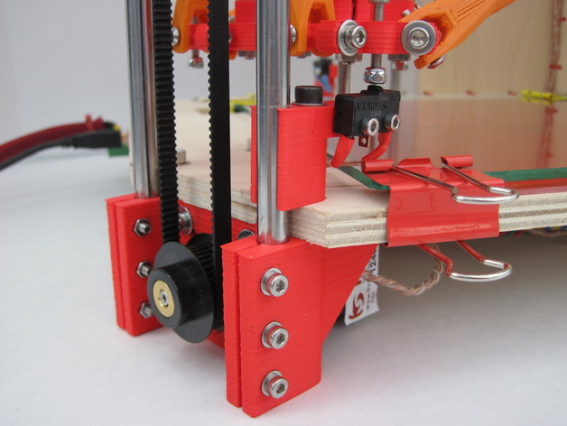
Very nice, but the connections to the gantry carts should be hinged to move up during a collision. Then you can put a microswitch on each with signals fed down to the end effector. The weight of the end effector will hold the hinged plates down during normal operation. This way you can detect collisions with either the heated plate or the part you are working on to do an e-stop. It could also be used to calibrate the platform by touching down in a sequence of spots around the heated plate.
I've been thinking about your design for a while and the same problem on my Makerbot. You can't rely on a calculated value to prevent a collision especially in the absence of encoders.
May I make a request? It would be nice if your suspension rods could be made in 2 pieces for those of us still w
orking on a 4" bed or just the rod ends so we can use carbon rods.
Thanks for your feedback! I have considered adding microswitches to the vertical carriages or suspension rods. The problem is that in order to activate the microswitch, the carriage needs a flexible hinge, but that would introduce backlash. The weight of the end effector (150 g) is not enough to keep the hinge down because I want to print very fast.
For calibration, I have added 3 bottom endstops around the print bed, see the new pictures that I uploaded today. All top and bottom endstops are now adjustable with M3 screws. I think it's good enough to calibrate all 6 endstops before each print. For all printers without encoders, a collision sh
ould never happen during a print. It's like motors skipping steps, or extruder jam, or power supply failure -- you can't prevent it completely but it's usually not a problem.
The rod.scad source file contains a module for the rod ends which works great with carbon fiber tube from the kite store. A
jig could help to align the rod ends and ensure they're all the same length when glued together.
Actually just load joint.scad in OpenSCAD and you should see the jaws() module for use with carbon fiber tube. Maybe I'll upload it as a separate thing to make it easier to find.
How come you decided to build three towers instead of four? I downloaded the files from git and wanted to start printing some parts, but then I noticed that the main file("rostock.scad") has a 4 tower design.
Anyway, great work!
See the older comment thread about 3 vs 4 towers at the bottom. I decided to start with three towers after all, to build the simplest design that could possibly work. Four towers might improve precision, but it also needs 33% more parts and it would be over-constrained. This means the mechanics might jam if the four sides are not coordinated exactly right. I should probably update the rostock.scad file to reflect the current status.

Interesting, but I think you will run into problems with vibrations and the overall stability of this design when you add the heavy extruder assembly.
That's why I'm planning to use bowden cables for the filament drive, similar to the Ultimaker design. The moving platform is going to be very light. The fully assembled MakerGear hotend weighs only 38 grams, and the heavy extruder motor (350 grams) doesn't need to move around because it's mounted to the frame, at the other end of the bowden cable.
Cool, I'd like to see it in action. Are you planning on building a prototype?
Yes, I want to build a prototype if I can find the time. My wife just had a new baby boy on Tuesday and our older two kids need my attention too. The good news is that my employer's giving me several weeks of paid paternity leave.
Because the four towers are identical, I'm currently ordering some parts for only one tower to start building and experimenting with it. My first Prusa build (from a MakerGear kit) should be ready to print soon, then I can start printing parts for Rostock.
I have posted the OpenScad sources on gi
thub and made an animated GIF that shows Rostock in action:
I think you need to re-do your linkages, this seems like it can only go up and down with no lateral movement. =-X
Agree! Neat idea but by the renderings it is locked in the X and Y direction and can only move in the Z direction... DONT_KNOW
...unless all connections to the platform are ball joints?
My new printable diagonal rods have universal joints instead of ball joints: http://www.thingiverse.com/thing:17917http://www.thingiverse.com/thi...

Exactly: the black carbon fiber rods (from the kite shop) have ball joints on both ends (which are cheaply available for model race cars).
Could this be accomplished with only 3 towers instead of 4? I know there is a lot of math involved using this method, would using less towers be more computationally intensive?
Yes, the same design also works with 3 towers (or more than 4). I'm planning to make a prototype with 4 pairs of rods because that's what the impressive speed record industrial delta robots use, and because I think that the additional pair of rods will improve positioning accuracy. It should be trivial to build an "economy" model with 3 towers instead of 4, with only small modifications to hardware and software.
I haven't run the numbers, but I expect that there isn't going to be a big increase in speed from an extra tower compared to, say, using more powerful motors. You may see better resolution and precision though.
The linked helium frog delta bot looks like it has 3 towers. I do wonder how clever the linkage has to be in order to keep the extruder level(ish) though.
The extruder platform is always level (within the tolerance of the ball joints) because of all those pairs of parallel carbon rods. See http://en.wikipedia.org/wiki/Delta_robothttp://en.wikipedia.org/wiki/D... and http://en.wikipedia.org/wiki/Parallel_robothttp://en.wikipedia.org/wiki/P... for details.
By using the site, you agree to the updated Terms of Use and Privacy Policy.


Please Login to Comment