smoothieware-website-v1
Your guide to installing Smoothieboard in a 3D printer
![]()
Probably the machine for which Smoothie is most used, due to Smoothie’s roots in the RepRap project, 3D printers are fairly simple to Smoothiefy.
This is a step-by-step guide to connecting your board to the various components of the 3D printer, configuring everything, from the beginning to actual printing.
This guide is a community effort, and this page is a Wiki. Please don’t hesitate to edit it to fix mistakes and add information, any help is very welcome.
On a typical 3D printer setup, installing a Smoothieboard will mean you do the following things:
- Read all of the guide before you start, best way to avoid mistakes
- Install some Software to talk to your board
- Install the Windows drivers if using that OS
- Connect your board via USB and practice talking to it
- Take a look at the configuration
- Upgrade your firmware to the latest version if you feel like it
- Wire your power supply and provide it with power
- Wire the power supply to Smoothieboard’s motor and mosfet power inputs
- Connect motors to the stepper motor driver outputs
- Edit your configuration to match your motors
- Test the motors, and admire your accomplishment for hours
- Connect Endstops to the endstop inputs
- Edit your configuration to match your endstops
- Test your endstops by homing the machine
- Connect your hotend and heated bed’s thermistors to the thermistor inputs
- Edit your configuration to match your thermistors
- Test that they read temperature correctly, admire a beautiful temperature graph
- Connect your hotend and heated bed’s heaters to the mosfet outputs
- Edit your configuration to tell Smoothie what to heat, with what mosfet and how
- Test that you can correctly control temperature on all heaters, carefully
- Connect, configure and test any fans you may have
- Connect, configure and test any probes you may have
- Setup calibration or leveling if relevant
- Configure your slicing software and slice a 3D file into a G-code file
- Use your host software to send your new G-code file to the Smoothieboard
- Watch as the machine prints using your new Smoothieboard system
- Be happy
This guide will walk through everything you need to accomplish to successfully perform these steps.
At the end of this guide, you should have a fully working machine.
Translations
Some users have hand-translated this page. Note that this translated version is by definition never going to be up-to-date. Use it to help you understand in general, but any specific information should be taken from the original version, especially before asking the community for help.
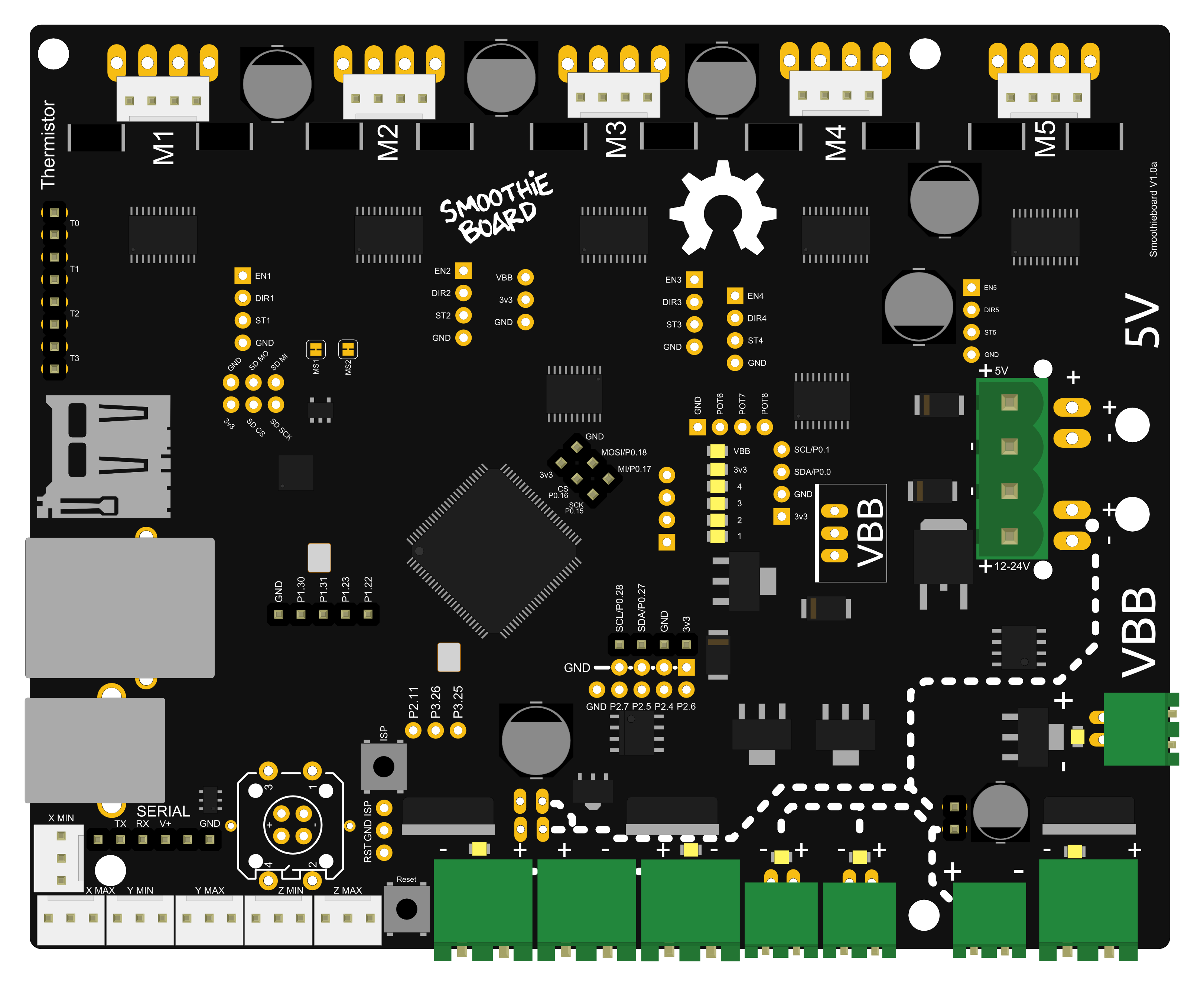
USB Connectors

Smoothie uses USB-B
Unboxing
Your Smoothieboard comes with a micro SD card in the microSD slot.
The boards come pre-flashed. With a basic configuration file installed on the SD card, no preparation is needed before you can connect Smoothieboard to your computer and start interacting with it.
The first thing you might want to do before you start connecting your board is to look at our list of Software, and install a “host” program to talk to the board.
[!WARNING] Don’t have a Smoothieboard? If you don’t have a Smoothieboard but have or consider purchasing an MKS board, please make sure you read What’s wrong with MKS
Connecting via USB
A good first step is to connect your board to your computer to familiarize yourself with it. Connect a USB-B cable to the USB connector on the board, and to your computer.
SD card

Files on your Smoothieboard's SD card
A moment after connection, your computer will recognize the Smoothieboard as a USB Mass Storage Device (like a USB disk-drive or an SD card reader), showing you the files present on the SD card. Drivers are needed for Windows 7/8, while Linux and Mac OS X directly support the device, you can find those drivers here.
This allows you to add, copy, edit, or delete any file you’d like. Already present on the SD card is a file named “config”. This file contains all of the configuration options for your board and is read when you start or reset your board. You edit the configuration simply by editing this file in a Text Editor, saving it, and resetting the board. No need to recompile or flash the board.
[!SUCCESS] You can read more about configuring your Smoothieboard at Configuring Smoothie
[!NOTE] The SD card can also be used to flash a more recent version of the firmware to your board, while the pre-flashed firmware should work this is not always the case, see where to get the binary file and how to flash it via the SD card.
It can also be used to store and play G-Code files, see Player.
USB Mass Storage is not the only thing you get when you connect the board. The board also exposes a USB CDC Serial interface, allowing you to send G-Code and receive answers. (There is also a DFU interface for flashing firmwares but that’s mostly for developers).
The CDC (Serial) interface is the interface host programs like Pronterface use to allow you to interact with your machine. If you are already familiar with it, you can try connecting right now and get an answer from the board. If not, we explain it all later in this guide.
Connecting via the network
Network

Hope you have fewer cables than this
The other main communication interface present on the Smoothieboard, apart from the USB port, is the Ethernet port, which allows you to connect your board to your local Ethernet network, and talk to the board via TCP/IP.
This is the same kind of technology you would find on a network-connected 2D printer, for example.
It allows you to access a web interface the board serves, and control the machine via your browser.
It also allows you to connect some software that supports it (like Pronterface and Visicut) to your Smoothieboard via the network.
Network is disabled by default but is very easy to enable and configure.
It is also the recommended main method of communicating with your Smoothieboard.
You can find all the information you need about using the network interface here: Network interface
Updating your firmware
Now that you have your board, a very good idea before starting is to update your firmware to the latest version.
You do this by downloading the latest firmware.bin file, copying it onto the SD card, and resetting the SmoothieBoard.
Then, the new firmware will “flash” (you will see the LEDs on the board do a little “dance”), and you will then have the latest version.
This is particularly useful if you ever need to ask for help, as people helping you will be assuming you have the latest version.
You can find the file, and information on how to flash it, at Flashing Smoothie Firmware.
Migrating
If you are migrating from another firmware, here are guides to help you understand how some values from your old firmware match the values in your new Smoothie system:
Warnings
Before you start wiring your machine’s elements to the board, there are several things you need to keep in mind and be careful about during all of the assembly.
Make sure you read this. Seriously. Not kidding. Do it. It’s important.
[!DANGER] Polarity
Note the inversion between the 5mm and 3.5mm connectors
Always make sure the polarity is correct when wiring in power inputs (coming from the Power Supply). Reversed polarity can damage or destroy all or part of your board. Polarity is indicated on the board itself by the + and - signs. Double check. On older versions of the board, markings are partially hidden by the connector, making it confusing. Rely on only the diagrams.
To check the polarity of your power source, attach your multimeter probes to the two wires of your power source respectively. If the voltmeter reading is positive it implies that the red probe is connected to the positive wire (+) and the black probe to the negative wire (-).
The main (labeled VBB) power input has a reverse polarity protection, however, it will not hold forever. As soon as you notice something is wrong, turn the power supply off and check again.

[!DANGER] Disconnecting
Never disconnect or connect stepper motors from the stepper motor drivers while the board is powered (i.e., when the Power Supply is turned on).
The drivers have very good protection against most possible problems and are very hard to destroy accidentally. But it is possible.
[!WARNING] Shorts
Be careful that nothing metallic ever touches the board while it is powered on. Falling screwdrivers, nuts and bolts can cause shorts and destroy the board. Check the board before powering it on. Do not press the reset button with anything metallic, as you could slip and cause a short, use a plastic screwdriver or the like.
[!WARNING] Use the right connector
Always check the schematic before connecting power sources (coming from the Power Supply) to the board. Connected to the wrong connector can destroy components. A common example of this problem is plugging a power input cable, into the connector for an output, or plugging the limit switches in backwards.
[!WARNING] Crimping
Make absolutely sure of your connections using crimps or screw terminals, from wires to any type of connector, are very careful and well done. Connections (to the stepper motors for example) lost while the machine is running can destroy your board.
[!DANGER] Markings
In the case of the VBB power input, be careful. If your board came with connectors pre-soldered, the 5mm connector is present, and the polarity of that connector is that of the large traces in the wiring diagram to the right (red is +, blue is -). On some boards, the marking on the boards may be hidden by the connector itself, so for VBB, do not rely on the markings on the board, but on the diagrams on this page. However, if you did not get your connectors soldered, and want to solder a 3.5mm connector instead of a 5mm connector, also note that the polarity is the opposite.
[!INFO] USB v Ethernet
USB can, in some setups, be subject to interference, which causes disconnections, and can ruin your work. This is very hard to prevent if it happens even in normal conditions. Ethernet, on the other hand, does not have this problem: save yourself the trouble, and use Ethernet right away. It’s very nice. See Network for information on how to set it up.
[!WARNING] Destroying your board
If you receive a bad board, you will get a replacement. But if you destroy your own board, your only options will be to fix it yourself (which can be quite difficult), or get a new one.
This is why it is very important you make sure you do not destroy your own board. Smoothieboard is reasonably protected, but there are still things that will destroy it. The general idea is: if a part of the board gets too much power, it will get destroyed. Here are some common mistake users do that cause the board to get too much power and die:
- Plugging 12-24v (motor power) into anything you are not supposed to. Like the 5V line, or an end-stop or thermistor input for example. Problems with the 5V or 3.3V power are not as much of a problem as the board is 5V-tolerant, so wrong connections and shorts should be okay as long as they do not last too long.
- Shorting 12-24v to anything else, which is essentially the same as plugging it into a place you are not supposed to (see above). This can happen by dropping a metal object onto the board, bad soldering, loose wires, un-protected wires, etc …
- Using an inductive load (like a motor, fan or solenoid) on a MOSFET, without a diode across (see Fan documentation).
The general idea here is: always make sure everything is clean, and double-check everything before turning the power on. You can not learn by making mistakes here, as mistakes will likely cost you your board.
Electrostatic discharge can also destroy your board : make sure you properly ground everything.
[!DANGER] Heater safety
If your machine contains any heating element and uses the temperature control module to control it, please make sure you read the section about implementing all safety measures here, and implement as many as you can. Fires will kill you if you don’t.
[!DANGER] Grounding
Make sure your machine’s case and electronics are properly grounded, also make sure your location’s electrical installation’s grounding is correctly done.
See for example:
[!WARNING] Environmental hazards
Be aware of your environment: it’s not just the machine itself.
- On a laser cutter, the machine vents large quantities of toxic smoke and gas, make sure it is very well evacuated to a place where no-one is breathing them
- On a CNC-mill, dusts, like wood dust for example, can be explosive if they come in contact with a flame, be careful and take measures to limit dust in the air
- On a 3D printer, the acetone used to clean things is very flammable, and the sprays used to increase bed adherence are explosive, store them adequately and be careful when using them
In particular, you are even more in danger if you are using your machine in a confined space, always be on the watch for safety issues.
For a good read about safety, you can refer to the RepRap Wiki documentation on the subject
To properly understand some of the safety instructions in this documentation, basic knowledge about electricity is required. See this page for a refresher on the basics.
Logic Power Inputs

There are different ways of providing logic power to your board.
Your board needs two sorts of power to work: 12-24V power to turn motors, heat hotends, etc., and 5V (or “logic”) power to power the microcontroller (the brain).
There are three ways to provide 5V power to the board:
- By plugging a USB cable in, USB cables provide 5V
- By soldering a voltage regulator to the board (and providing 12+24V, which the voltage regulator then turns into 5V)
- By providing 5V directly to the 5V power input (next to the VBB power input)
If you want to keep it simple, the easiest solution is just to connect your Smoothieboard to your computer via USB.
Note you can connect several different power supplies at the same time, with no issue at all. Smoothieboard has diodes on-board that will simply get the power from the one with the highest voltage, meaning you can even turn one off and the other will be used without a reset.
If voltage and current are strange concepts to you, it’s probably a good idea before you continue setting up your board, that you read this introduction.
The board’s logic circuits (5V line) typically consume up to 500mA current (what is standard for a USB port).
Main Power Input
Without power, your board can not do much. The board uses power to operate the control logic and to move stepper motors, and power heating elements, fans, and others.
How to choose a power supply unit (PSU)
Two power supplies are required, 5.0V and ‘bulk’ power (VBB).
5.0V supply
- Voltage (V): The 5.0V supply should be regulated to 5% tolerance (4.75V to 5.25V). This supply provides power for the control logic circuitry, and should be a good quality regulated power supply (which is inexpensive). Using a cheap buck regulator from a higher voltage is not recommended, as ever exceeding 5.5V on this supply may instantly and permanently damage the control logic on your Smoothieboard.
- Current (A): The 5.0V supply should be rated to supply at least 1A continuous current (or more). Typical load is roughly 0.5A.
VBB supply
- Voltage (V): VBB can be from 12 to 24V. While most of the components on the Smoothieboard are rated up to 32V, it is not recommended or supported to use that high of a voltage. 12V PSUs are more common, and generally cheaper. However, the higher the voltage, the higher performance you can get from your stepper motors. This is the reason some designers use 24V PSUs. However, be careful that with a 24V PSU, you will need 24V fans, and will need to reduce the PWM setting for your heating elements or (preferred, and safer) use 24V heating elements.
- Current (A): The total current required is the current for each stepper motor, plus the current for every peripheral on your machine Smoothieboard will control. This depends on your machine type. On a typical 3D printer, you can safely consider 10A to be sufficient for the heated bed, and 10A or a bit less for the rest of the loads. Go for a 17 to 20A PSU if you have a heated bed. 7A to 10 is probably enough if you do not have a heated bed (or if you are setting up a CNC mill or a laser cutter). If you bought your machine as a kit, a PSU with appropriate current is most probably provided (or one is recommended). If building your machine yourself by self-sourcing, the documentation for the machine model will also most probably recommend a current rating. A power supply that is able to supply more current than is needed is not a problem. Having not enough current to drive your hot-end, heater bed, or motors is a problem.
General Notes
Multiple-output power supplies are available. In some cases, a minimum load must be applied to the primary output before the secondary output will be regulated to within tolerances. For example, a dual 5.0V and 12V supply might regulate the 5.0V well at no-load conditions, but the 12V output may be low until power is drawn from the 5.0V supply.
EMI Filtering
Electromagnetic Interference (EMI): Digital logic and power circuitry (such as stepper motor drivers) switches currents and voltages on and off very rapidly. This produces EMI proportional to the voltage, current and rate of switching. EMI can be radiated (as radio waves) and/or conducted through the power line cord or other connections. EMI can interfere with (produce noise in or prevent proper operation of) other equipment, including sensors and motion encoder modules. To reduce these effects, an EMI filter module may be added to help reduce the conducted emissions. An EMI filter module may not strictly be needed, however it is often simpler to take protective measures from the start rather than e.g. searching for the cause of strange, intermittent behavior or coming back to failed 3D prints for months – and then put in an EMI filter module.
Fuses / Circuit Breakers
A typical US AC wall outlet provides 110V to 120V and is protected by a fuse or circuit breaker with a 15A or 20A rating. As (for example) a motor load such as a refrigerator or saw briefly draws a much higher starting current, in order to avoid ‘nuisance trips’ a 20A rating does not instantly remove power when that load is exceeded.
A VBB power supply rated (for example) 12V at 10A can provide up to 12V x 10A = 120W (Watts) of DC power. Power supplies are not 100% efficient, thus it will require 5% to 30% more than 120W of input power to produce 120W of output power. It is usually safe to assume at least 70% efficiency at full load (higher for more modern supplies), so the power supply will only need perhaps 1.5A at 120VAC input. A 1A, 5V supply will require much less than 1A at 120VAC input.
While the equipment can only use perhaps 2.5A, the AC wall outlet will provide at least 15A to 20A continuously without tripping the circuit breaker or blowing the fuse. It would be possible (though rare) for a fault condition that drew for example 10A at 120V = 1200W to occur, which would be a fire hazard, without tripping the breaker. If you wish to address this possibility, adding an additional fuse and/or circuit breaker with (for example) a 3A rating in line with the AC ‘hot’ wire will ensure that if there is a lot of excess power being drawn due to a circuit failure, then this fuse will blow or circuit breaker trip, and power will be removed. Too low a fuse or circuit breaker rating will result in ‘nuisance’ trips.
Setup
Make sure you use a Regulated Power Supply, make sure you connect the ground wire for the mains to the power supply, and if it has a fan, make sure it has sufficient space around it to let air flow and cool it appropriately.
To wire the power supply unit to mains (wall AC power), make sure you connect the right colored wires to the right connectors on the PSU. The 3 connectors are “live”, “neutral” and “ground”. Color changes from cable to cable. You can find charts for your specific country/cable on the internet, but the following colors are the most common:
| Standard | Load/live color | Neutral color | Earth color |
|---|---|---|---|
| US | Black | White | Green |
| Europe | Brown | Light blue | Yellow/Green |
Once the wires connected to the PSU, make sure none of your computers is doing something important (like a system upgrade). In case something goes wrong, plug the PSU into a power strip with an on/off button. Then turn that button ON. If your house loses power, you did something wrong. If an LED illuminates on the PSU, everything is fine: unplug the PSU and continue.
If you are new to wiring, please check our how to wire guide.
[!DANGER] NEVER manipulate mains (220/110V) power wires while they are plugged into the wall plug. Unpleasantness and/or death are common consequences of not respecting this rule.
[!DANGER] Ground your printer’s frame by connecting it to the Earth terminal on your power supply. In the (unlikely) event that a power supply wire comes undone and touches the printer’s frame, this will prevent you from getting an unpleasant and/or deadly shock.
Now that the PSU is getting mains power, your PSU is converting it into 12V or 24V DC (Direct Current) power. You need to connect wires from it to the Smoothieboard to provide power.
The most important thing for DC is to respect polarity: + goes to +, - goes to -. On the PSU, + terminals are indicated as +, V+, 12V+ or 24V+. Ground (-) terminals are indicated as -, V-, COM or GND.
On the Smoothieboard they are indicated simply as + and -.

By convention, black (sometimes brown) wires are used for ground, and red (sometimes orange, white or yellow) wires are used for power connections.
You may want to turn on the power supplies and test the output voltages before connecting them to the Smoothieboard (and turn them back off before connecting).
Once the wires are correctly connected, you can turn the PSU ON. If everything was done correctly, the red LED (marked VBB) on the Smoothieboard will light up brightly.
[!WARNING] If the VBB LED does not light up, immediately turn the PSU off. Check polarity, and check all the connections are strong and properly done. When you turn the PSU on, make sure you are ready to immediately turn it back off.
Now that the board has power, you can use that power to move things!
Emergency stop
It is recommended you setup an emergency stop button on your machine, so that in case of a problem, you can easily and quickly turn the machine off. For information on how to do this, please read EmergencyStop.
Stepper Motors
A bit of theory:
« A stepper motor (or step motor) is a brushless DC electric motor that divides a full rotation of the motor into a number of equal steps. The motor’s position can then be commanded to move and hold at one of these steps without any feedback sensor (an open-loop controller). » (Wikipedia)
Because they work by steps, and you can accurately control how many steps you move in each direction, stepper motors are a very practical way of moving things to a desired position. This makes them great for most CNC applications.
Smoothie comes with stepper motor drivers designed for bipolar stepper motors, with a maximum current rating of 2 Amps.
[!IMPORTANT] There is a very wide variety of stepper motors around. Bigger motors are generally more powerful. For a given size, motors will have different torques, max speeds, and different capacities to maintain torque as speed increases.
It is important you choose the right motor for your application. The most common mistake is to choose a high inductance motor. There are two main “families” of motors out there: high inductance motors are mostly designed for maintaining position and moving rarely (like on a telescope mount), and low inductance motors are designed for moving often, and at high speeds (like on a CNC mill or 3D printer).
If you use a high inductance stepper motor with a Smoothieboard (or any “CNC” stepper motor driver), not only will you get bad speed/torque performance, but when moving the stepper motor (or axis) by hand, very high voltage will be generated, which can destroy your stepper motor driver.
You can recognize a “high inductance” stepper motor by the fact that it’s rated inductance is high, in general higher than
10mHis bad. If your motor doesn’t tell you its inductance, rated voltage is also an indication: high inductance stepper motors usually have high rated voltages, a typical value being12V, where “CNC” steppers have voltage below 5V. This is not what you want, you want a low inductance stepper motor, with an inductance ideally below 10mH, and a rated voltage ideally below 5VThe reprap community defines a good stepper motor like this:
Ideal stepper is (for reprap printers and similar small CNC using microstepping drivers on 12-24v supply) NEMA17 size, rated 1.5A to 1.8A or less, 1-4ohm winding resistance, 3 to 8 mH, 62oz.in (0.44Nm, 4.5kg.cm) or more of torque, 1.8 or 0.9 degrees per step (200/400 steps/rev respectively), for example the kysan 1124090/42BYGH4803 or the rattm 17HS8401 or Wantai
 Be careful you get the coils right
Wiring
Direct wiring
Bipolar stepper motors have two poles (bi-polar). Each pole is connected to two wires. That’s 4 wires coming out of your stepper motor. These have to be connected to your Smoothieboard.
Each stepper motor driver on the Smoothieboard has 4 connections to that effect. (Stepper motor drivers are labeled M1, M2 etc…)
The tricky thing is often to find out which wires connect to which poles. If you just wire things at random, you have a chance it will work, but let’s be scientific about it. Several methods:
- Documentation: Look at your motor, find its part number. Then google it. If you are lucky, you will find a schematic or a data-sheet that will indicate which wire goes to which pole. Note the colours that correspond to each coil.
- Fingers: When the two wires for a given pole touch together, a closed circuit for that pole is created. This makes the stepper motor more difficult to turn. You can use that effect to discover the poles. Turn the stepper motor shaft, it should turn freely. Now take two wires, and make them touch. Turn the shaft again. If it shows resistance, is harder to turn, you found a pole. If it doesn’t, keep one wire, and try another one for the second one. Do this until you find a combination that shows resistance. Once you find the two wires for a given coil, the other two wires are simply the other coil. Note the colours that correspond to each coil.
- Multimeter: Configure your multimeter to read resistance. Then the method is the same as the previous one, take two wires at random, test them, except you know you find a coil when you measure electrical resistance between two wires. If you measure no contact, try another wire combination. Note the colours that correspond to each coil.
Now to connect the wires to the Smoothieboard. Let’s call one coil A, and the other coil B. It doesn’t matter which is which. Polarity also doesn’t matter, all it changes is the direction the motor turns, and you can change that in the configuration file. Now simply connect your two wires to the Smoothieboard’s 4 pins for that stepper motor driver as such: AABB or BBAA. Other combinations like ABBA or ABAB will not work.
 If you don’t get it right, it won’t work properly
Once your stepper motor is properly connected to your Smoothieboard, it is ready to be controlled.
 In this example, a stepper motor is connected to the M1 driver, and power is provided to VBB (the main power input).
External Stepper driver
If you want to use larger stepper motors than the Smoothieboard’s drivers can handle (2A max), you need to use external stepper drivers.
You can find detailed information on how to wire an external stepper motor driver to a Smoothieboard in the External driver appendix.
 They often have useful information on them
Configuring
Example configurations are available on GitHub.
You can also refer to the Configuration documentation.
Current
The first thing you have to do is tell the stepper motor drivers what is the current rating for your stepper motors is. To drive the stepper motor correctly, the driver has to know the motor’s current rating.
Each stepper motor model has a precise current rating. You can drive your stepper motor at a lower current, which will make it more silent, but also less powerful. But you cannot drive the motor at a higher current than it is rated at. This would cause overheating, and possibly skipped steps.
The rating is often written on your stepper motor’s label (see picture on the right). If it is not, you can get it by googling the stepper motor model number, or by contacting your seller or manufacturer.
Once you have the correct rating, you can set the corresponding parameter in the configuration file.
Smoothie has a funny way of naming stepper motor drivers. Instead of naming them X, Y or Z, because this makes no sense in non-cartesian robots like delta robots, we name the drivers using Greek letters so they are arm application agnostic:
| Label on the Smoothieboard | M1 | M2 | M3 | M4 | M5 |
|---|---|---|---|---|---|
| Axis in a Cartesian machine | X (left-right) | Y (front-back) | Z (up-down) | E0: First extruder | E1: Second extruder |
| Greek letter | α (alpha) | β (beta) | γ (gamma) | δ (delta) | ε (epsilon) |
| Current setting configuration option | alpha_current | beta_current | gamma_current | delta_current | epsilon_current |
Now, as described in the “Unboxing” paragraph, connect the board to your computer, open the “config” file with a text editor, and change the configuration value for each stepper motor driver to the correct value.
For example, if your alpha stepper motor has a current rating of 1.68A, edit the corresponding line to read:
alpha_current 1.68 # X stepper motor current
Do this for each stepper motor you have to connect to the board. (If you have a Cartesian robot, see which motor connects to which stepper driver in the array above. If you use another type of arm solution, see the specific documentation.)

Steps per millimeter
A stepper motor driver operates in steps. It moves a certain number of steps in one direction, then a certain number of steps in another. You think in millimeters. You want your machine to go to a certain position in millimeters, then another position in millimeters.
You need Smoothieboard to convert the millimeters you ask of it, into steps the stepper motor driver understands.
That conversion depends on your exact arm solution. The most common, and the simplest, is the Cartesian arm solution, and it is the one we will focus on here. Documentation for other arm solutions can be found separately.
In the case of a Cartesian arm solution, you simply convert a certain number of millimeters to a certain number of steps. That is the steps_per_millimeter configuration option that you have to set for each stepper motor.
To compute it, you must multiply a certain number of factors.
- The object you move moves a certain number of millimeters for each rotation of the stepper motor. (This depends on the characteristics of the belt/pulley, or lead-screw system you are using.)
- The stepper motor moves a certain number of full steps per rotation. That is usually 200. (But it can be 400.)
- Each step is divided by the stepper motor driver into a certain number of microsteps. It is that number, and not the number of full steps, that we want. Smoothieboard V1.1 always divides steps into 32 microsteps. (16 for older smoothieboards).
The formula is as follows:
steps per millimeter = ((full steps per rotation) x (microsteps per step)) / (millimeters per rotation)
To help you, there is an awesome calculator by the awesome Josef Prusa: http://calculator.josefprusa.cz/
Once you know the correct value for a given stepper motor driver, set it in the config file.:
alpha_steps_per_mm 80 # Steps per mm for alpha stepper
Do this for each stepper motor driver.
In the case of your extruder stepper motor, the principle is the same, but the value is extruder_steps_per_mm.
Here are two good videos about steps-per-millimeters:

Direction
It is now time to test your stepper motors. For this, you will need to use host software like Pronterface or the web interface.
Now connect to your Smoothieboard over the serial interface. Power your machine on by plugging the PSU into the wall.
Now you need to move an axis to make sure the stepper motor is turning in the right direction. In Pronterface, click near the yellow arrow marked “+X”.
Your X axis will move. If it moved to the right, great! Everything is fine, and you have nothing to change. If it moved to the left, you need to invert the direction of that axis.
You do this by editing the configuration file, and inverting the direction pin for that stepper motor driver:
alpha_dir_pin 0.5 # Pin for alpha stepper direction
Becomes:
alpha_dir_pin 0.5! # Pin for alpha stepper direction
This is for your axes. In the case of your extruder, the config value is extruder_dir_pin.
Save the config file, reset the Smoothieboard, connect again using Pronterface. Now the axis will move in the right direction.
Do this for each axis.
[!WARNING] If you have a moving bed in the Y axis for example, as opposed to a moving tool, be careful: what matters is the direction of the head relative to the bed, not the direction of the bed relative to the machine. It’s very common to get confused and invert your Y axis on moving bed machines (or not invert it when it should be). Basically, if an asymmetrical object looks like the model when it is printed, then your Y axis is correct, otherwise you need to change your configuration.
Arm Solutions
On a typical “Cartesian” machine, each actuator (a motor and a linear rail, named alpha, beta, gamma) corresponds to an axis (like X, Y, and Z).
However, on other machines, the position in Cartesian space (X, Y, Z) must be converted, using math, into a more complex position for the actuators.
This is the case, for example, of linear delta (often just called “delta”) machines.
Currently, Smoothieware supports the following arm/motion solutions:
- Cartesian
- Delta (Linear Delta)
- Rotary Delta
- Hbot (CoreXY)
- Morgan Scara
To configure your machine for the right type, see its specific page.
Extruder
Extruders are used to push plastic filament through a hotend, to achieve the awesome feat of 3D Printing.
This module controls the motor that pushes the filament, it does not take care of the hotend itself, which is the job of TemperatureControl.
The most important parameter to get your extruder module to work properly, is extruder.[module-name].steps_per_mm.
You can create as many Extruder modules as you want (although you may run out of memory and Smoothie will no longer boot), as long as you give them different module names. You can name those modules whatever you want (as long as you stick to only alphanumerical characters). NOTE that the default build of Smoothie only supports 2 extruders (5 axis), if you need 3 extruders you need to compile with make AXIS=6.
Configuration
Steps per millimeter
We need to find the number of steps the stepper motor drivers have to generate in order to move the filament 1 millimeter.
This value depends on your stepper motor, the microstepping on your stepper motor drivers, the gear reduction ratio on the extruder assembly if any, and the diameter of your hobbed pulley/bolt.
A very good guide on how to find this value can be found here: Triffid Hunter’s Calibration Guide
extruder.hotend.steps_per_mm 140
Filament diameter
This is an optional parameter for those who want to use volumetric extrusion, but are too lazy to do their own math. ;) Simply enter the machine’s filament diameter here and set your slicer’s filament diameter to 1.128379mm (2*sqrt(1/pi)) and enjoy portable gcode! Further explanation can be found in Triffid Hunter’s guide, linked above.
[!WARNING] In the current edge builds, when a filament diameter is specified either from M200 Dxxx or the config setting Smoothie expects all E values specified to be in mm³, so when you click extrude 10mm in Pronterface Smoothie will actually extrude 10mm³. And E values in a gcode file will all be expected to be mm³. Note that when firmware retraction is specified via M207 the retraction length is still in mm not mm³, but will be converted to mm³ based on the filament diameter at the time of extrusion.
In the current master builds, only print moves have E specified in mm³, retract or extrude only moves are still in mm. The change in edge is to be more compliant with other firmwares and user expectations.
extruder.hotend.filament_diameter 3.0
The filament diameter can also be saved at runtime with this M code:
M200 |
Set E units for volumetric extrusion - D |
M200 D3.0 |
and saved with M500.
Firmware Retract
G10/G11 will cause the filament to retract and unretract, this option can be set in most current slicers.
Note this is optional, you are not obligated to set this up, but it is a nice feature if you want to use it.
The amounts of extrusion and speed can be set with the following M codes:
M207 |
set retract length S[positive | mm] F[feedrate | mm/min] Z[additional | zlift/hop] Q[zlift | feedrate mm/min] | M207 S4 F30 Z1 |
M208 |
set retract recover length S[positive | mm surplus to the M207 S*] F[feedrate | mm/min] | M208 S0 F8 |
or can be set in config with the following settings:
extruder.hotend.retract_length 3 # retract length in mm
extruder.hotend.retract_feedrate 45 # retract feedrate in mm/sec
extruder.hotend.retract_recover_length 0 # additional length for recover
extruder.hotend.retract_recover_feedrate 8 # recover feedrate in mm/sec (should be less than retract feedrate)
extruder.hotend.retract_zlift_length 0 # zlift on retract in mm, 0 disables
extruder.hotend.retract_zlift_feedrate 6000 # zlift feedrate in mm/min (Note mm/min NOT mm/sec)
These can be set differently for each extruder defined.
[!WARNING] Please note the inconsistency here with the config specifying mm/sec and the M206/207 specifying mm/min. Sorry about that.
Pins
As all stepper motors, the extruder stepper motor needs 3 pins to be controlled: step, direction, and enable (See Pin Reference and Pinout):
1st Extruder (delta, or M4)
extruder.hotend.step_pin 2.3
extruder.hotend.dir_pin 0.22
extruder.hotend.en_pin 0.21
[!WARNING] These pins are for the delta (4th) driver on a Smoothieboard. This is what is most commonly used, but in another board or setup, you may have to use other pins.
2nd Extruder (epsilon, or M5)
extruder.hotend2.step_pin 2.8
extruder.hotend2.dir_pin 2.13
extruder.hotend2.en_pin 4.29
[!WARNING] These pins are for the epsilon (5th) driver on a Smoothieboard. This is what is most commonly used, but in another board or setup, you may have to use other pins.
[!TIP] You can do special things to Smoothie pins, for example, you can invert them, which is useful to revert the direction of your extruder if it is wired the wrong way around on your board, see Pin Configuration.
You can make your extruder module use any other stepper motor driver, or even an external stepper motor driver, simply by providing the adequate pins for that driver, see Pinout.
Current
On boards which feature current control of the stepper motor drivers (Smoothieboard or 4pi), you have to set that value for the extruder too.
This is handled by the Currentcontrol module, but usually, the line for the configuration of a given stepper motor is written along with its pins, for clarity.
delta_current 1.5
Set the value to the exact value your stepper motor is rated for (or less, for less noise, but less torque).
Setting the current to a value higher than the recommended one causes overheating, and skipped steps.
Example
Here is an example of a common configuration and wiring of an extruder with a Smoothieboard.
This example setup is of an extruder (stepper motor) connected to the M4 stepper motor driver.
If your machine has multiple extruders, you also want to look at multiple-extruders.
Configuration
The default Smoothie configuration example contains an example extruder section, this means you do not need to create a new one, but you can just re-use the sample one.
The configuration looks like this:
## Extruder module configuration
# See http://smoothieware.org/extruder
extruder.hotend.enable true # Whether to activate the extruder module at all. All configuration is ignored if false
extruder.hotend.steps_per_mm 140 # Steps per mm for extruder stepper
extruder.hotend.default_feed_rate 600 # Default rate (mm/minute) for moves where only the extruder moves
extruder.hotend.acceleration 500 # Acceleration for the stepper motor mm/sec²
extruder.hotend.max_speed 50 # Maximum speed in mm/s

extruder.hotend.step_pin 2.3 # Pin for extruder step signal
extruder.hotend.dir_pin 0.22 # Pin for extruder dir signal (add '!' to reverse direction)
extruder.hotend.en_pin 0.21 # Pin for extruder enable signal

delta_current 1.5 # Current setting in Amperes for this motor driver
Now that your extruder is configured, you can wire it:
Wiring
Wiring your extruder stepper motor is very similar to how you wire your X, Y, and Z stepper motors (see adequate documentation): you just wire the 4 wires of the stepper motor, to the output connector of the M4 stepper motor driver.
 It contains a thermistor and a heating element in its heating block
Temperature control
In a 3D printer, you heat thermoplastics. There are two different parts in which you want to do that. First, the hot-end heats the plastic to the point where it is liquid enough to go through the nozzle. Second, the heated bed (in only some printers), on which the first layer is deposited, is heated to allow for better sticking of the plastic to the bed, and more uniform temperature in the part while printing.
For detailed information about temperature control in Smoothie, you can look at this part of the documentation: TemperatureControl
The process is essentially the same to wire and control a hot-end, or a heated bed, and is as follows:
Thermistor
A thermistor’s resistance changes with temperature. By reading that resistance, we can determine the temperature of a hot-end or a heated bed.
This allows Smoothie to turn the heater on or off depending on the temperature it reads, to achieve the desired temperature.
 There are 4 of them, close to the SD card slot
To wire the thermistor, take the two wires from the thermistor on your hot-end or heated bed, and connect them to one of the pairs of thermistor inputs on the Smoothieboard. Each input is two pins, one for each thermistor wire. There is no polarity to respect.
Smoothieboard has 4 thermistor inputs total, meaning a line of 8 pins on the edge of the board. Polarity is not important for thermistors.
[!WARNING] The Smoothieboard has two grounds: a normal Ground, shared with the motors and everything else, and a special Analog Ground, which is isolated from the rest, to protect the very sensitive ADCs (analog to digital converters) used to read temperatures.
When reading temperature, never use the normal ground to read temperatures, always use the AGND connections provided on the thermistor inputs.
This also means you cannot “share the ground” on wires going to your hotend, as some users sometimes do to “save wires”. This is a very bad idea and will cause a lot of problems.
By convention (meaning that if you wire things according to the way it is specified in the default configuration file, you do not need to edit the configuration file as it will already be correct),
- Hot-end thermistor connects to T0
- Heated bed thermistor connects to T1
In the default configuration file, the thermistor pins are set up using that convention:
temperature_control.hotend.thermistor_pin    0.23             # Pin for the thermistor to read (here T0)
temperature_control.bed.thermistor_pin       0.24             # Pin for the heated bed to read (here T1)
You can, however, use any thermistor pin you want for any temperature control module you want.
 They come in all shapes and sizes
Thermistor Choice
Different models of thermistors are used in hotends or heated beds, and each type translates temperature into resistance differently. It’s essential to inform Smoothie about the specific thermistor model you have to ensure accurate temperature readings.
This configuration is done using the thermistor option in the configuration file. You provide the name of your thermistor, and Smoothie will handle the math accordingly.
temperature_control.hotend.thermistor EPCOS100K
Currently, Smoothie recognizes the following thermistor models:
| Name | Beta for 0-80°C | Beta for 185-230°C | I for Steinhart Hart | J for Steinhart Hart | K for Steinhart Hart | Part number |
|---|---|---|---|---|---|---|
EPCOS100K |
4066 | 4193 | 0.000722378300319346F | 0.000216301852054578F | 9.2641025635702e-08F | B57540G0104F000 |
Honeywell100K |
3974 | 4385 | 0.000596153185928425F | 0.000231333192738335F | 6.19534004306738e-08F | 135-104LAG-J01 |
Semitec |
4267 | 4375 | 0.000811290160145459F | 0.000211355789144265F | 7.17614730463848e-08F | 104GT-2 |
Honeywell-QAD |
0.000827339299500986F | 0.000208786427208899F | 8.05595282332277e-08F | 135-104QAD-J01 | ||
Semitec-104NT4 |
0.000797110609710217F | 0.000213433144381270F | 6.5338987554e-08F | 104NT-4R025H42G | ||
RRRF100K |
3960 | |||||
RRRF10K |
3964 | |||||
HT100K |
3990 |
Unknown Thermistor
If your thermistor is not recognized by Smoothie, you can define the parameters manually in the configuration file using either the beta value or the Steinhart Hart algorithm.
Using Beta Values
Set the beta value in the configuration file:
temperature_control.hotend.beta 4066 # set beta for thermistor
[!WARNING] Beta values provided by manufacturers are typically for the 0-80°C range, which can result in readings being about 7-10°C too high for the 185-230°C range. This makes beta values generally suitable for heated beds but not for hotends.
If the thermistor is 100K ohms at 25°C, this setting is usually sufficient. Additional settings like r0, t0, r1, r2 are not typically needed as the defaults work well.
If you’re unsure about your thermistor model, contact the designer or seller of your 3D printer, hotend, or heated bed to obtain the specifications and beta value.
Using the Steinhart Hart Algorithm
This is the preferred method. Set the Steinhart Hart coefficients in the configuration file:
temperature_control.hotend.coefficients 0.000722376862540841,0.000216302098124288,0.000000092640163984
To determine the Steinhart Hart coefficients for your thermistor, please refer to the SteinhartHart page.
Alternatively, if you have the temperature curve for your thermistor, you can define three points on that curve and let Smoothie calculate the coefficients:
temperature_control.hotend.rt_curve 20.0,126800,150,1360,240,206.5
Heating element
Now that Smoothie can read the temperature, it needs a way to heat things and maintain a desired temperature. This is the heating element. On a hot-end, that is usually a resistor or a cartridge heater, on a heated bed, that is usually a PCB plate designed to have the right resistance, or a kapton heated bed.
Because of its resistance, when power is applied to a heater, the heater consumes energy to generate heat.
These heating elements need to be connected to Smoothieboard on a port that allows Smoothie to turn them ON or OFF as needed. This is done by the use of MOSFET that takes a digital input signal, and, depending on its value, lets current pass or not.
[!WARNING]
If it will burn your skin, don’t touch it. Simple.
Smoothie has up to 6 MOSFET controls (6 on 5X, 4 on 4X, and 2 on 3X). The MOSFETs act as switches to ground: loads must be connected between the power source and the MOSFET switched terminal. When the MOSFET is switched on, power will be applied to the load. When the MOSFET is switched off, power will be removed, because one load terminal will be essentially disconnected and current cannot flow. The exception being inductive load ‘flyback’ switching transients, discussed above.
Connect your PSU to the power input connector for those FETs (providing power to the load), and connect your power-consuming element (be it heating element, spindle, etc.) between the power output terminal and the MOSFET terminal. Smoothie connects/disconnects the element’s ground as needed to maintain temperature or as requested by G-codes.
There are three main pairs of MOSFETs on the board:
- Big MOSFET pair: Their outputs are labeled P2_7 and P2_5 on the schematic, the input connector for them is found between them. They are found on the 4X and 5X boards. To power those MOSFETs, you need to provide them with power by wiring their power input to the power supply.
- Small MOSFET pair: Their outputs are labeled P2_6 and P2_4 on the schematic, the input connector for them is found by their side, between P2_6 and P1_23. They are found on all of the boards. To power those MOSFETs, you need to provide them with power by wiring their power input to the power supply.
- Mixed MOSFET pair: Their outputs are labeled P1_22 and P1_23 on the schematic. The pair is called “mixed” because it consists of one big MOSFET and one small MOSFET. They do not have a specific input, they take power directly from VBB (the Stepper motors power input described in the Stepper Motors chapter). To power those MOSFETs, you need to provide them with power by wiring their power input (which is the same as the one for the stepper motors) to the power supply.
[!TIP] Contrary to other boards, Smoothieboard does not have a single power input, but multiple power inputs.
This allows you to use different voltages for different things if you want, and makes it easier to use more current as the current is shared between more connectors. It does mean wiring one or two more connectors though.
If you are trying to control MOSFETs and they are not turning on, make sure you provided power to their power input.
MOSFETs list:
| MOSFET group | MOSFET name | Controlling pin | Output connector | Input method | Voltage | Current |
|---|---|---|---|---|---|---|
| Big MOSFETs | First big MOSFET | 2.7 |
X15 | Big MOSFETs power input X13 | 12-24V | 12.5A max |
| Big MOSFETs | Second big MOSFET | 2.5 |
X10 | Big MOSFETs power input X13 | 12-24V | 12.5A max |
| Small MOSFETs | First small MOSFET | 2.4 |
X7 | Small MOSFETs power input X6 | 12-24V | 3A max |
| Small MOSFETs | Second small MOSFET | 2.6 |
X8 | Small MOSFETs power input X6 | 12-24V | 3A max |
| Mixed MOSFETs | Third big MOSFET | 1.23 |
X16 | VBB (motor) input | 12-24V | 12.5A max |
| Mixed MOSFETs | Third small MOSFET | 1.22 |
X9 | VBB (motor) input | 12-24V | 3A max |
MOSFETs diagram:

[!WARNING] MOSFET power inputs have a polarity, make sure you connect
+on that connector to+on your PSU, and-to-on the PSU. Heater elements, however, do not have a polarity, so you do not have to worry about polarity on the outputs. If you are using another output element like a Peltier or a Spindle, you need to be careful to respect the polarity for the outputs too.
Never use the big MOSFETS for more than 12.5A (and monitor connector and MOSFET temperatures at that current use, too much heating can be a sign of a bad wire connection), and the small MOSFETS should never be used for more than 3A.
Trying to power a 40W (or more) hotend cartridge heater at 12V with the small FETs will destroy them, usually locking (melting) them to the “ON” state (shorted) and possibly destroying the circuitry driving the MOSFET gate.
If you need to control more than 12 Amps, you cannot do it with one of the MOSFETS on board, however, you can use a Solid State Relay. For information see the Solid State Relay Appendix on this page.
[!NOTE] In the case of both the Big MOSFETS pair and the Small MOSFETS pair, you take power from the PSU (Power Supply Unit) to them via their respective power input connectors.
There is an alternative, however (for currents up to 2 Amps or 4 Amps). For each pair, you can use jumpers (one jumper for the small MOSFETS pair (JP28), two parallel jumpers for the two big MOSFETS pair (JP11 and JP27)). If you solder the pins for those OR connect a jumper to those pins, closing the circuit to VBB (the stepper motors power input), allowing you to take the power from those MOSFETS from the same place as the stepper motors do.
In the case of the big MOSFETS, you have to solder and put in place two jumpers, in parallel, in order to handle more current.
[!WARNING] However, WARNING, each jumper is rated for only 2A of current. This means you cannot use this way of powering your MOSFETS if you are going to use more than 2A (for the small MOSFETS) or 4A (for the big MOSFETS, with both jumpers used, for 2 x 2A).
Do not use the jumpers to power a heated bed, for example, as it uses much more than 4A.
 Often made out of a rigid, or flexible (kapton) PCB
Example
Let’s say you want to connect a heated bed to your Smoothieboard. First, wire the thermistor to the thermistor input. Then, find out (from the Internet, or your seller/manufacturer) the current rating for that heated bed. In this example it will be the classical RepRap PCB plate Heatbed.
Ours has an 11A current rating, this means we cannot use it with a small MOSFET, and we need to wire it to a big MOSFET.
We connect our PSU to the power input for the big MOSFETS pair (don’t forget to check the labels on the board for polarity).
Then we connect the two wires from the PCB bed to one of the big MOSFETS out. Polarity is not important here.
Because this is the heated bed, we connect it to the P2_7 (pin 2.7 in the configuration file). This is a convention: it is configured that way in the default configuration file, meaning that if you connect it there, you do not need to change the configuration file to specify where you are connecting it: the configuration file is already correct.
For the hot-end, the default output is P2_4 (pin 2.4 in the configuration file).
To set a different MOSFET output for the bed or the hot-end, you have to edit the configuration file to the digital output pin corresponding to your chosen MOSFET. These are the lines you would have to edit:
temperature_control.hotend.heater_pin        2.7              # Pin that controls the heater cartridge for the hot-end
temperature_control.bed.heater_pin           2.5              # Pin that controls the heated bed
To help you figure out what is what, here is a recapitulating table:
MOSFETs Table
| MOSFET Pair | Big MOSFETS | Small MOSFETS | Mixed MOSFETS | |||
|---|---|---|---|---|---|---|
| Label on diagram | P2_7 | P2_5 | P2_4 | P2_6 | P1_23 | P1_22 |
| Digital output pin | 2.7 |
2.5 |
2.4 |
2.6 |
1.23 |
1.22 |
| Power Input | Between P2_7 and P2_5 |
Between P2_6 and P1_23 |
Taken from VBB | |||
| Size | Big | Big | Small | Small | Big | Small |
| Maximum current | 12A | 12A | 3A | 3A | 12A | 3A |
| Used by default for | Heated bed | Hotend 0 | Fan | Hotend 1 |
Testing
Once your thermistor is connected, and both the power input and the heater elements are plugged in, you are ready to test your temperature controller.
To do this, reset your Smoothieboard, then connect to it using host software like Pronterface, or using the web interface.
Now connect to your Smoothieboard over the serial interface. Power your machine on by plugging the PSU into the wall.
If anything burns or smells funny, turn everything off immediately and investigate.
The heaters are off by default when Smoothie starts. Check that they are not heating (one indication of the heater being ON is if the LED near the MOSFET is lit up, the other being checking the heater itself), if they are heating, something is wrong, turn everything off immediately and investigate.
Now, in Pronterface, set the temperature for either your bed or your hot-end, depending on what you are testing (wire and test only one at a time for easier problem investigation) at a low temperature (20°C above room temperature is a good idea), and monitor temperature to see if the temperature rises. If it does rise, everything is fine. If not, turn everything off immediately and investigate.
Once you know the heater works correctly, there is still some tuning to do: tuning your PID settings.
PID

It’s not very refined
PID is important. Without PID, a simple way to control temperature would be:
- If temperature too cold, turn heater on
- If temperature too hot, turn heater off
But there is a big problem with that method. Due to temperature not traveling instantly in what you heat from the heater to the thermistor, when the thermistor reads a given temperature, the heater is already hotter than what the thermistor reads. And that overshooting is something we do not want. It means reaching temperatures that could be undesirable, and it means you will not be able to correctly stabilize the temperature.
The solution to this is PID. It uses some math, allowing us to correct those problems by turning the heater on and off in a smarter sequence.
The P, I, and D factors are configured as follows:
temperature_control.hotend.p_factor     100
temperature_control.hotend.i_factor     0.1
temperature_control.hotend.d_factor     100
But the really tricky thing is to find the right values for these 3 factors: the default ones are most probably wrong for your setup. So unless you have been given those values with your hardware, or you are a PID grand-master, you will need some help:
[!WARNING] Do not try to use PID settings from Marlin as they are not compatible.
PID autotuning
PID Autotuning
Smoothie can automatically tune (find) your P, I, and D factors using a process described here.
Here is an example of the G-code command used to launch PID autotune:
M303 E0 S190
E0is the number of the heater or bed temperature control module, determined by the order that they appear in the config file. Here it would be 0 for the hotend, and 1 for the bed.S190is the temperature to autotune for. Use the temperature you will be using your heater at in real life. For a hotend here we use 190°C.
When you run the command, tuning begins:
Target: 190.0
Start PID tune, command is M303 E0 S190
T: Starting PID Autotune, M304 aborts
ok
T:  21.3/190.0 @80 1 0/8
T:  22.0/190.0 @80 1 0/8
T:  22.3/190.0 @80 1 0/8
T:  22.1/190.0 @80 1 0/8
Etc...
It continues for 3 to 8 cycles, heating up, cooling down. Then:
Cycle 4: max: 246.189, min: 227.627, avg separation: 0.418274
	Ku: 34.9838, Pu: 39.85
	Trying:
	Kp:  21.0
	Ki: 1.053
	Kd:   105
PID Autotune Complete! The settings above have been loaded into memory, but not written to your config file.
Now edit your configuration to use those three values (Kp is p_factor, Ki is i_factor, Kd is d_factor), reset, and temperature control should work much better. (Also M301 can be used to set the PID values and saved with M500)
Alternatively, you can also enter the following G-code:
M500
Which will save the configuration values automatically in a configuration override file.
Learn more about configuration overrides here.
[!WARNING] Do not send
M303over the web interface, use Telnet, Pronterface, or any other serial terminal. If sent over the web, the answers will accumulate in Smoothie’s RAM and may crash it.
Heater safety
There are features you can configure to make sure that your temperature control module will detect when something is wrong, and stop the machine when that happens.
It is a good thing to read about these, and configure them as best as you can, because your house burning down is a very bad thing.
It is also a good thing to configure it well, because if you do not, it is possible Smoothie will think there is a problem when there is none, which can be annoying.
You can read more about temperature control safety here.
Example setup
This information is all very abstract.
Here is an example setup for a simple 3D printer with one hotend and one heated bed:
In this setup:
- The heated bed is 12A at 12V, or 144W
- The hotend is 3A at 12V, or 36W
We are going to use the first big mosfet to control the bed, it has a current limit of 12.5A so we are within limits.
We also need to provide power to the first big mosfet via the big mosfet power input.
We cannot however use the second big mosfet for anything, because if we did, we would go over the 12.5A limit of the big mosfet power input’s connector.
This is because the input must provide power to both outputs, so if we were for example to connect a 12.5A load to the first big mosfet, and a 2.5A load to the second big mosfet, the total passing through the big mosfet input would be 15A, which is over the 12.5A limit.
Therefore, we will use the first small mosfet to control the hotend. 3A is well within its limit.
Here again, we need to provide power to the small mosfet, via the small mosfet power input.
This means we will make 4 connections:
- Connecting the heated bed to the first big mosfet output
- Connecting the power supply to the big mosfet power input
- Connecting the hotend to the first small mosfet output
- Connecting the power supply to the small mosfet power input
 Note how the mosfets need power provided to their power inputs

It’s essentially just a switch
Endstops
End-stops are small interrupters that you put at the end of each of your axes. When you boot your machine up, Smoothie has no way of knowing the position of each axis. When it starts a print, Smoothie moves the axis until it touches that interrupter, and when it is hit, it declares that that is position 0 for that axis. And does so for all axes.
This allows Smoothie to then precisely know where everything is relative to that initial position. It is quite convenient as it saves you the hassle of actually moving the machine into that position when you want to start a print. Automation is great.
However, end-stops are not necessary, you could do without them. They are just so convenient that most machines use them.
End-stops can also be used as limit switches which prevent the machine from attempting to move beyond the physical limits of the axis (by pausing/stopping movement when triggered), see the Endstops page for details about configuring Smoothie to use End Stops as limit switches.
[!NOTE] To make things as simple as possible: In Smoothie, endstops do three things:
- Homing (move til endstop is hit)
- Hard endstops (stop when endstop is hit, which is optional)
- Soft endstop (once homed, do not go further than a set position, which is also optional)
[!WARNING] Smoothie does not allow you to use a zprobe as an endstop. An endstop must be dedicated to being an endstop and cannot be used as a zprobe and vice versa. This does not mean ANY kind of feature is missing, you can still do everything you expect, this is just a subtility in vocabulary and in how configuration is organized, that new users are generally fine with, except if they come from another system which has a different paradigm.

There are 6 of them, two for each axis
Mechanical endstop wiring
This will concentrate on the most common type of end-stops: the mechanical ones. Other types exist like optical or hall-o sensors.
[!WARNING] There are plenty of fun and futuristic endstop types around: optical, laser, magnetic, force-sensitive, infrared, inductive, etc…
However, please note that the general feedback from the community, is that most of those are either less precise, less repeatable, or much more difficult to get to “work right”, compared to the classical “mechanical” endstop.
The mechanical endstop is actually likely the most precise, repeatable and easy to get to work option you have at your disposal. Just because these other options exist and have been explored by the community, does not mean they are better.
You might happen have a good reason to use a fancy endstop, but if you don’t, it’s likely a good idea to stick with a mechanical one.
Mechanical end-stops are simple interrupters: when not pressed, they do not let the current pass, when pressed, they let the current pass. By connecting a digital input pin on the Smoothieboard to the interrupter, and connecting the other side of the interrupter to Ground, the Smoothieboard can read whether or not it is connected to Ground, and therefore whether or not the end-stop is pressed.
Most mechanical end-stops have 3 connection points, to which you have to attach your wires:
- C: Common
- NO: Normally Open, meaning it is not connected to C when the interrupter is not pressed, and connected to C when the interrupter is pressed.
- NC: Normally Closed, meaning it is connected to C when the interrupter is not pressed, and not connected to C when the interrupter is pressed.

You want to connect the Signal (green in the schematic) and Ground (blue in the schematic) pins for the end-stop on the Smoothieboard, to the C and NC connection points on the end-stop.
[!NOTE] For each endstop, we connect C to Signal and NC to Ground because this means the digital input pin (endstop connector) will be connected to Ground in its normal state and cut from Ground when the button is pressed. This approach is less prone to noise than the reverse. See here for more information.
Another positive effect of this approach is, that if a wire breaks for some reason you get the same signal as if the endstop is pressed. That makes sure that even with a damaged wire you are not able to overrun the endstop.
[!DANGER] Make absolutely sure that you do not connect VCC (red) and GND (blue) to a mechanical (microswitch) endstop! Depending on your wiring this may fry your smoothieboard instantly or when the switch gets pressed. There is certain wiring where this won’t happen when you switch the signal between VCC and GND, but if you’re not careful enough you will damage your board.
You want to connect your X end-stop to the X min pins, Y end-stop to the Y min pins, and Z end-stop to the Z min pins.
Powered endstops wiring
Mechanical endstops are simple switches, they simply let a signal pass through, or not, allowing us to detect their status with an endstop input. It has no intelligence of its own.
There are more sophisticated endstops. Those are “powered endstops”, for example: Hall-O (magnetic) or optical endstops.
The only difference between a mechanical endstop and those powered endstops is that they require being provided with 5V power.
This means that where for a mechanical endstop you connect the Signal and GND pins, for a powered endstop, you connect the Signal, GND and 5V pins.
Other than this, it works exactly the same as a mechanical endstop: The Signal pin receives something different depending on whether the endstop is triggered or not.
Different powered endstops have different behaviors:
Some connect Signal to Ground when triggered, and Signal to 5V when not triggered.
Others connect Signal to 5V when triggered, and Signal to Ground when not triggered.
To know exactly what your endstop does, see its documentation.
If once wired, your endstop reports the opposite of what it should via the M119 command (1 when triggered/pushed, and 0 when not triggered), see the “Testing” section.
Some endstops might require removing their “pull-up” configuration, in this case, change:
alpha_min_endstop 1.28^
To:
alpha_min_endstop 1.28
And if you need it to be a pull-down, change it to:
alpha_min_endstop 1.28v
In some very rare cases, the endstop reading circuit on the Smoothieboard will not be adequate for your endstop type. In this case, you should use a “free” GPIO pin on the Smoothieboard that nothing else uses to connect your endstop to.
See Pinout to find adequate pins.
Testing
The default configuration most probably already has everything you need: the pins are already correct and the default speeds are reasonable.
Once they are wired, you can test your end-stops.
To do this, reset your Smoothieboard, then connect to it using host software like Pronterface or the web interface.
Now connect to your Smoothieboard over the serial interface. Power your machine on by plugging the PSU into the wall.
Now in Pronterface, home one axis by clicking the small “home” icon for that axis. Begin with X, then Y, then Z.
If your axis moves until it hits the end-stop, then stops when it hits it, moves a small distance back, then goes a bit slower back to the end-stop and stops, that end-stop is working fine.
On the other hand, if the axis moves a small distance in the wrong direction, then stops, you have a problem: your Smoothieboard always reads the end-stop as being pressed. So when you ask it to move until the end-stop is hit, it reads it immediately as pressed and stops there.
Another problem can be that the axis moves and never stops, even after the end-stop is physically hit. This means your Smoothieboard actually never reads the end-stop as being pressed.
There is a command that allows you to debug this kind of situation: in Pronterface, enter the “M119” G-code.
Smoothie will answer with the status of each endstop like this:
X min:1 Y min:0 Z min:0
This means: X endstop is pressed, Y and Z endstops are not pressed.
Use a combination of this command, and manually pressing end-stop, to determine what is going on.
If an end-stop is read as always pressed, or never pressed, even when you press or release it, then you probably have a wiring problem, check everything.
If an endstop is read as pressed when it is not, and not pressed when it is, then your end-stop is inverted.
You can fix that situation by inverting the digital input pin in your configuration file. For example if your X min endstop pin is inverted, change:
alpha_min_endstop 1.28^
To:
alpha_min_endstop 1.28^!
Here is the exact mapping of pin names to inputs on the Smoothieboard:
| Endstop | X MIN | X MAX | Y MIN | Y MAX | Z MIN | Z MAX |
|---|---|---|---|---|---|---|
| Config value | alpha_min | alpha_max | beta_min | beta_max | gamma_min | gamma_max |
| Pin name | 1.24 | 1.25 | 1.26 | 1.27 | 1.28 | 1.29 |
More information can be found here.
Fans
Fans are important: they help you cool things down. On a 3D printer there are two main things you need to cool:
First, most often your hot-end’s “cool” part (the top of it) needs to be cooled so heat does not accumulate there and transfer to the rest of the machine and damage it.
Secondly, you often (in the case of printing PLA) need to cool down the top layer currently being printed by your machine so that heat does not accumulate in the printed part and cause mayhem.
While the first one is usually safest being always powered on, the second one you want digital control via MOSFETs, as most modern slicing software allows for smart control of that fan.
Always ON fan
For the fan that is always ON, all you need is to find power somewhere to power it.
You can wire it directly to your PSU (+ goes to +, - goes to -), but there is also a little trick if you want to wire it to your Smoothieboard.
If you add the jumper to JP28 like described in the MOSFETs section of the Temperature Control section of this tutorial, then the connector usually used for providing power to the small MOSFETs, will actually output whatever power is provided to the VBB (stepper motors) connector.
This means you can simply add this jumper, then connect your fan to the small MOSFETs power input (X6).
Digitally controlled fan
You do not need a big MOSFET to control a fan. One of the small MOSFETs is more than enough. See the Temperature Control section to identify which you want to use and which GPIO pin corresponds to that MOSFET.
Then, you need to edit your configuration file to add (or alter) this section:
# Switch module for fan control
switch.fan.enable                            true             #
switch.fan.input_on_command                  M106             #
switch.fan.input_off_command                 M107             #
switch.fan.output_pin                        2.4              # The pin matching the MOSFET we chose
switch.fan.output_type                       pwm              # PWM output settable with S parameter in the input_on_comand
#switch.fan.max_pwm                           255              # set max PWM for the pin default is 255
Now wire the fan to the output for that MOSFET (here it is the first small MOSFET, using pin 2.4), make sure you respect polarity.
 The fan is wired to the output for the first small mosfet (watch the polarity, and make sure you always add a diode when wiring a fan), and the small mosfets are getting power via their power input. (NB Note - newer revisions of the Smoothieboard now come with the Diodes installed on the Small Mosfets - do a visual check to confirm)
You can now control your fan digitally: issue the M106 G-code to turn it on, and M107 to turn it off. Those are also the commands slicing software generates to control fans.
[!WARNING] Fans (and other active loads like solenoids, mechanical relays, motors, anything with a coil) can feed power back into the MOSFET and destroy it.
You likely will be fine for fans with current ratings below 0.25Amps (most common types), however, while it is common practice to omit the diode under that rating, we still require you install one for safety. (Understand: if you do not install a diode and burn your MOSFET because of it, it will be considered user error.) Above this, you need to install a diode across the MOSFET’s power output as you are pretty much guaranteed to burn the MOSFET without one. (NB Note - newer revisions of the Smoothieboard now come with the Diodes installed on the Small Mosfets - do a visual check to confirm)
 Note starting with Smoothieboard version 1.1, you do not need to do this anymore on the first two small mosfets, as the diodes are there by default.
 The diode should be installed with the white band (negative side of the diode) soldered to the + (positive side) of the power output, and the other side to the - (negative side) of the power output. Good diodes to use are: 1N5819 or SS