smoothieware-website-v1
Pin list
| ARM Pin | mBed Pin | LPCXpresso Pin | Assignment | Comment |
|---|---|---|---|---|
| P0.0 | P9 | 9 | i2c1 sda | Internal I2C bus. Used for digipots and port expander. |
| P0.1 | P10 | 10 | i2c1 scl | Internal I2C bus. Used for digipots and port expander. |
| P0.2 | USBTX | 21 | uart0 txd | Used for ISP programming of the bootloader and for debugging. |
| P0.3 | USBRX | 22 | uart0 rxd | Used for ISP programming of the bootloader and for debugging. |
| P0.4 | P30 | 38 | alpha_en_pin | |
| P0.5 | P29 | 39 | alpha_dir_pin | |
| P0.6 | P8 | 8 | spi1 ssel | sdcard |
| P0.7 | P7 | 7 | spi1 sck | sdcard |
| P0.8 | P6 | 6 | spi1 miso | sdcard |
| P0.9 | P5 | 5 | spi1 mosi | sdcard |
| P0.10 | P28 | 40 | beta_en_pin | also i2c2 sda |
| P0.11 | P27 | 41 | beta_dir_pin | also i2c2 scl |
| P0.15 | P13 | 13 | spi0 sck | User spi port. used for rrd glcd |
| P0.16 | P14 | 14 | spi0 ssel | User spi port. used for rrd glcd cs |
| P0.17 | P12 | 12 | spi0 miso | User spi port. |
| P0.18 | P11 | 11 | spi0 mosi | User spi port. used for rrd glcd |
| P0.19 | - | Pad17 | gamma_en_pin | also i2c3 sda on lpcxpresso e2prom |
| P0.20 | - | Pad18 | gamma_dir_pin | also i2c3 scl on lpcxpresso e2prom |
| P0.21 | - | 23 | delta_en_pin | |
| P0.22 | - | 24 | delta_dir_pin | lpcxpresso led |
| P0.23 | P15 | 15 | hotend.thermistor_pin | |
| P0.24 | P16 | 16 | bed.thermistor_pin | |
| P0.25 | P17 | 17 | thermistor2 | |
| P0.26 | P18 | 18 | thermistor3 | |
| P0.27 | - | 25 | i2c0 sda | User i2c port. sd cd on rrd glcd adapter |
| P0.28 | - | 26 | i2c0 scl | User i2c port. sd cs2 on rrd glcd adapter |
| P0.29 | 31 | 37 | USB-D+ | |
| P0.30 | 32 | 36 | USB-D- | |
| P1.0 | eth txd0 | |||
| P1.1 | eth txd1 | |||
| P1.4 | eth tx en | |||
| P1.8 | eth crs | |||
| P1.9 | eth rxd0 | |||
| P1.10 | eth rxd1 | |||
| P1.14 | eth rx err | |||
| P1.15 | eth ref clk | |||
| P1.16 | eth mdc | |||
| P1.17 | eth mdio | |||
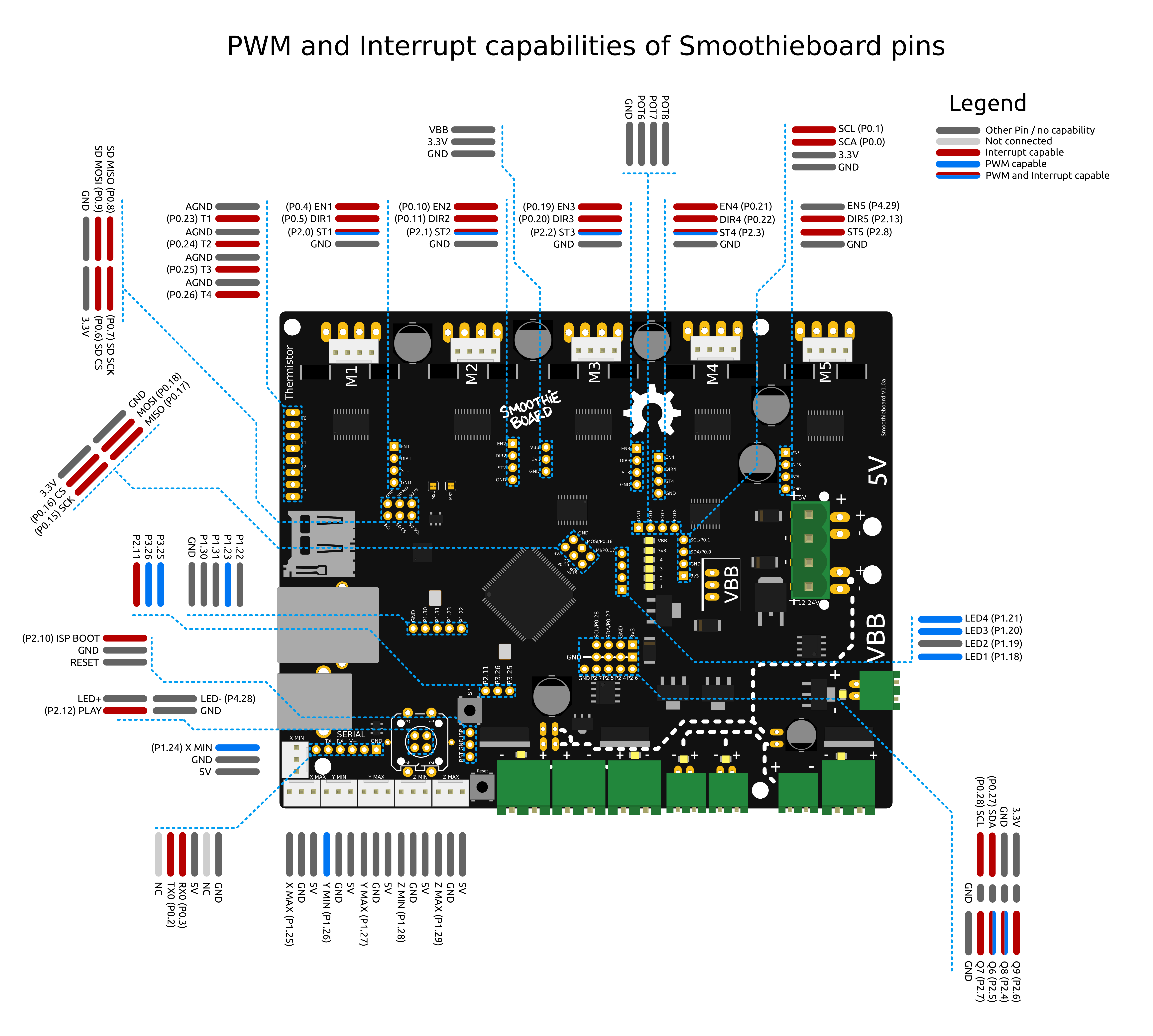
| P1.18 | LED1 | Pad1 | led1 | h/w PWM capable. can be free if leds_disable is set true in config. |
| P1.19 | - | Pad2 | led2 | can be free if leds_disable is set true in config. |
| P1.20 | LED2 | Pad3 | led3 | h/w PWM capable. can be free if leds_disable is set true in config. |
| P1.21 | LED3 | Pad4 | led4 | h/w PWM capable. can be free if leds_disable is set true in config. |
| P1.22 | - | Pad5 | 3rd small fet | spare on 3 and 4 driver boards |
| P1.23 | LED4 | Pad6 | 3rd large fet | spare on 3 and 4 driver boards, h/w PWM capable |
| P1.24 | - | Pad7 | alpha_min_endstop | h/w PWM capable |
| P1.25 | - | Pad8 | alpha_max_endstop | |
| P1.26 | - | Pad9 | beta_min_endstop | h/w PWM capable |
| P1.27 | - | Pad10 | beta_max_endstop | |
| P1.28 | - | Pad11 | gamma_min_endstop | |
| P1.29 | - | Pad12 | gamma_max_endstop | |
| P1.30 | P19 | 19 | spare | used for click button on rrd glcd |
| P1.31 | P20 | 20 | spare | used for buzzer on rrd glcd |
| P2.0 | P26 | 42 | alpha_step_pin | h/w PWM capable |
| P2.1 | P25 | 43 | beta_step_pin | h/w PWM capable |
| P2.2 | P24 | 44 | gamma_step_pin | h/w PWM capable |
| P2.3 | P23 | 45 | delta_step_pin | h/w PWM capable |
| P2.4 | P22 | 46 | psu.output_pin | h/w PWM capable |
| P2.5 | P21 | 47 | bed.heater_pin | h/w PWM capable |
| P2.6 | - | 48 | fan.output_pin | |
| P2.7 | - | 49 | hotend.heater_pin | |
| P2.8 | - | 50 | epsilon_step_pin | spare on 3 and 4 driver |
| P2.9 | - | Pad19 | USB soft connect | |
| P2.10 | - | 51 | ISP button | |
| P2.11 | - | 52 | spare | used for pause/kill/back pin on glcd |
| P2.12 | - | 53 | kill button | Hardwired in Bootloader as ISP button and in kill module as pause button |
| P2.13 | - | 27 | epsilon_dir_pin | spare on 3 and 4 driver |
| P3.25 | - | Pad13 | spare | used for encoder pin for all panels, h/w PWM capable |
| P3.26 | - | Pad14 | spare | used for encoder pin for all panels, h/w PWM capable |
| P4.28 | - | Pad15 | play/pause led | |
| P4.29 | - | Pad16 | epsilon_en_pin | spare on 3 and 4 driver cannot be used in opendrain |
[!NOTE] The following pins are hardwired and would need to be changed in source code
P0.2P0.3,P0.6-P0.9,P0.29,P0.30,P2.9,P2.10,P2.12The rest are configurable in config. Some pins are also setup as outputs and changed in the Bootloader and those are not configurable, these pins are…P1.18,P1.19,P1.20,P1.21,P4.28,P2.4,P2.5,P2.6,P2.7However once booted these can be reassigned if needed.
P0.*andP2.*can be setup as interrupt enabled pins.
LPC176x ADC channels and pins
| Adc Channel | Port Pin | Pin Functions | Associated PINSEL Register |
|---|---|---|---|
| AD0 P0.23 | 0-GPIO, | 1-AD0[0], 2-I2SRX_CLK, 3-CAP3[0] | 14,15 bits of PINSEL1 |
| AD1 P0.24 | 0-GPIO, | 1-AD0[1], 2-I2SRX_WS, 3-CAP3[1] | 16,17 bits of PINSEL1 |
| AD2 P0.25 | 0-GPIO, | 1-AD0[2], 2-I2SRX_SDA, 3-TXD3 | 18,19 bits of PINSEL1 |
| AD3 P0.26 | 0-GPIO, | 1-AD0[3], 2-AOUT, 3-RXD3 | 20,21 bits of PINSEL1 |
| AD4 P1.30 | 0-GPIO, | 1-VBUS, 2- , 3-AD0[4] | 28,29 bits of PINSEL3 |
| AD5 P1.31 | 0-GPIO, | 1-SCK1, 2- , 3-AD0[5] | 30,31 bits of PINSEL3 |
| AD6 P0.3 | 0-GPIO, | 1-RXD0, 2-AD0[6], 3- | 6,7 bits of PINSEL0 * not available on Smoothieboard |
| AD7 P0.2 | 0-GPIO, | 1-TXD0, 2-AD0[7], 3- | 4,5 bits of PINSEL0 * not available on Smoothieboard |
[!WARNING] ADC pins are not 5v tolerant.
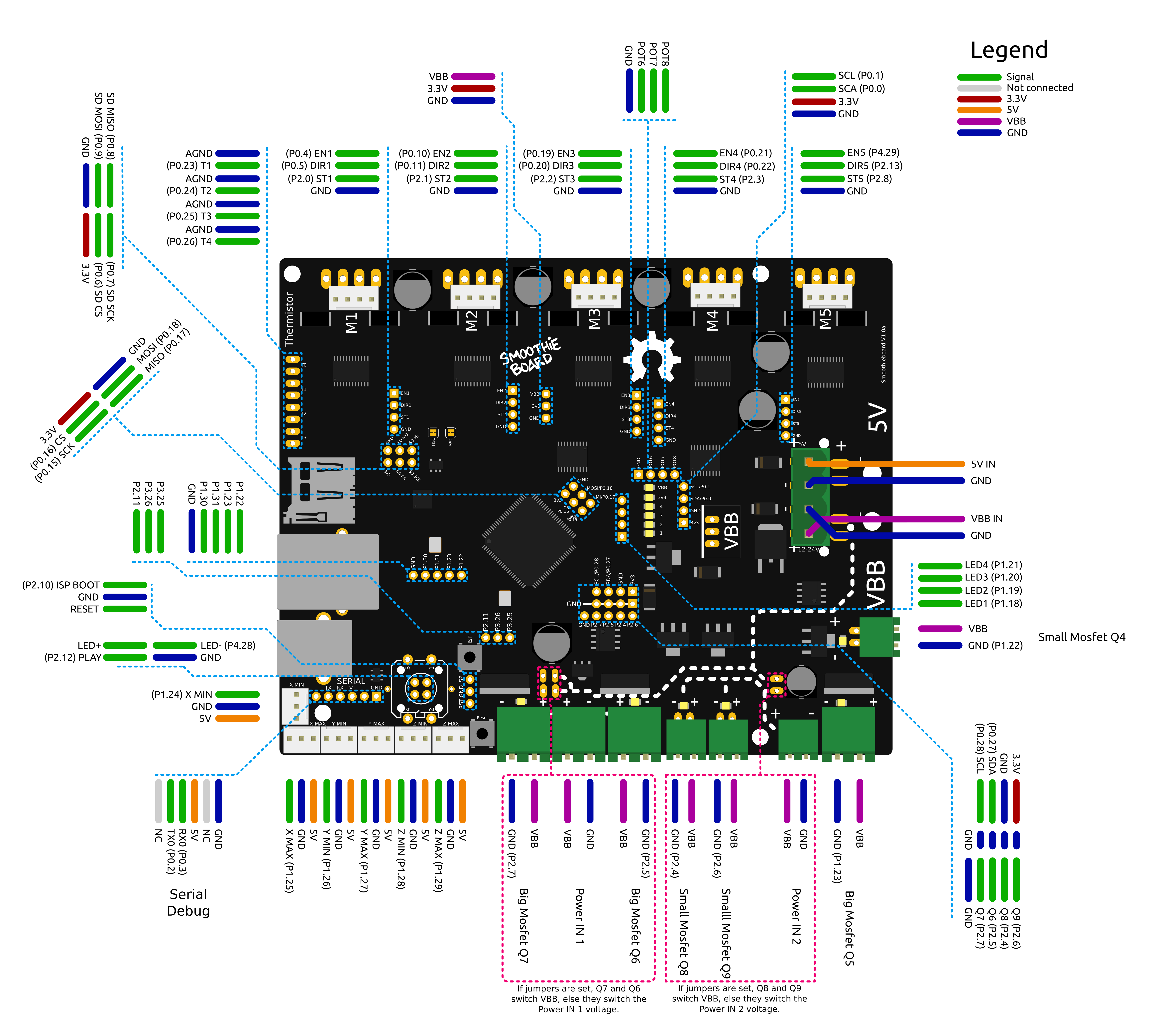
Pinout
[!NOTE]

[!NOTE]
Also see the pin usage table

Notes:
- Do not use endstop inputs as outputs (for example to control a solid state relay), this will not work.