smoothieware-website-v1
Printing, milling or cutting from the SD card
Printing, milling or cutting from the SD card on Smoothieboard is easy. First, you transfer your gcode files to the card. You can do this by moving the SD card to your computer and copying the files to it or simply copy the files to the card when it mounts on your desktop. If it isn’t mounting automatically, you are probably running Linux and have automount disabled. You can change that or manually mount it. The other option is to use the built-in Web Server if you have installed the RJ45 connector and an ethernet connection to the board. You can upload files to the SD card with this convenient Web interface.
Now, with your gcode files on the SD card, there are a few options to run it from there:
[!NOTE] Serial terminal You can use a serial port terminal application like CoolTerm (it supports OSX, Windows, Linux) or Cutecom (OSX and Linux). Once connected, enter
helpto get a list of supported console commands.If you use Pronterface with your 3D printer, you can use its built-in serial terminal feature - just prefix serial commands with an “@”. So, once connected to smoothie send
@helpand it will list all of the available commands.You can find more information about using the
playcommand here.You can also use the
M24G-code to play files from the SD card, see Supported G-codes.
[!NOTE] Web interface Another option is to use the Web interface mentioned above.
[!NOTE] Panel If you have a panel (like the RepRapDiscount GLCD) you can use the panel menus to run/pause/stop printing your gcode files.
Wiring
How well your machine is wired is going to determine how long it lives and how resistant it is to breakage.
We have a great guide on different techniques and recommendations, please read the how to wire page.
Crimping connectors
If your Smoothieboard came with connectors, you got connector casings, and crimps. You will need to attach your crimps to your cables, and then insert the crimps into the connector casings.
This tutorial is a good read about crimping properly.
[!WARNING] Please be careful and patient, if you have never done it before you will probably fail a few times before getting the hang of it. Also be careful to insert the crimp into your connector the right way around.
Soldering connectors
Please read this comic before soldering anything.
Using two steppers motor on a single driver
Stepper motor drivers on Smoothieboard can handle up to 2Amps per driver.
If you want to control two separate motors with a single driver ( for example you have two stepper motors for your Y axis like on a Shapeoko, or two stepper motors for your Z axis like on a Reprap Prusa i3 ) and have both motors move simultaneously, you have two options.
If the total of the current used by your motors is more than 2Amps ( for example two 1.5Amps motors are 3Amps ), you can not wire them together on a single driver, and you need to look at doubling drivers just below.
However, if your total current is less than 2Amps, you can wire both motors in parallel to a single driver.
To do so, find for each stepper motor, which wires match which coils, and wire the same coils into the stepper motor connections on the Smoothieboard ( two wires per connection, one from each motor, for each pin ).
If when you test it, the two motors turn in reverse, you need to reverse one of the coils of one of the stepper motors, and they will start turning in the same direction.
You also need to set a current value for that driver that matches the total current your two motors will be using. For example if the motors are each 0.8Amps, your total is 1.6Amps and you need to set for that specific driver ( here gamma driver is shown ) :
gamma_current 1.6
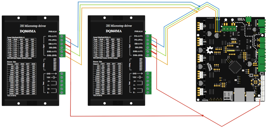
Doubling stepper motor drivers
If you need to drive two motors with a single axis, but the total current used for the motors is more than 2Amps ( for example two 1.5Amps motors add up to 3Amps ), you can not wire the steppers in parallel to a single driver and have it control both motors at the same time like described above.
This is the case for example for the Y axis of Shapeoko machines.
In this case, you will need to use one driver for each of your motors. This means you need a Smoothieboard with one more stepper motor driver than you have axes. If you have 3 axes and need to double one, you will need a 4X or a 5X Smoothieboard.
To enslave a driver to another, you will need to connect the control pins for both drivers together.
For example if you want the epsilon ( M5 ) driver to be the slave to the gamma ( M3 ) driver you will need to connect:
- EN3 to EN5
- ST3 to ST5
- DIR3 to DIR5
The connectors for this can be found close to the stepper motor drivers, and are labelled.
Finally you need to do two things in your configuration file:
First, set the current value for both drivers. For example if you are using gamma and epsilon set:
gamma_current       1.5
epsilon_current      1.5
Then, you need to make sure that none of the step, dir and enable configuration values for your slave stepper motor driver, are present in the configuration file.
For example if you are using gamma as a slave, make sure that none of the following values are present in the configuration file:
gamma_step_pin
gamma_dir_pin
gamma_en_pin
If they are, remove them. And be careful, for the delta driver, if you started from the 3D printer configuration file, they are not referred to as delta_xxx_pin but as extruder_xxx_pin, if they are present you must remove them all.
Only remove the lines for the slave driver.
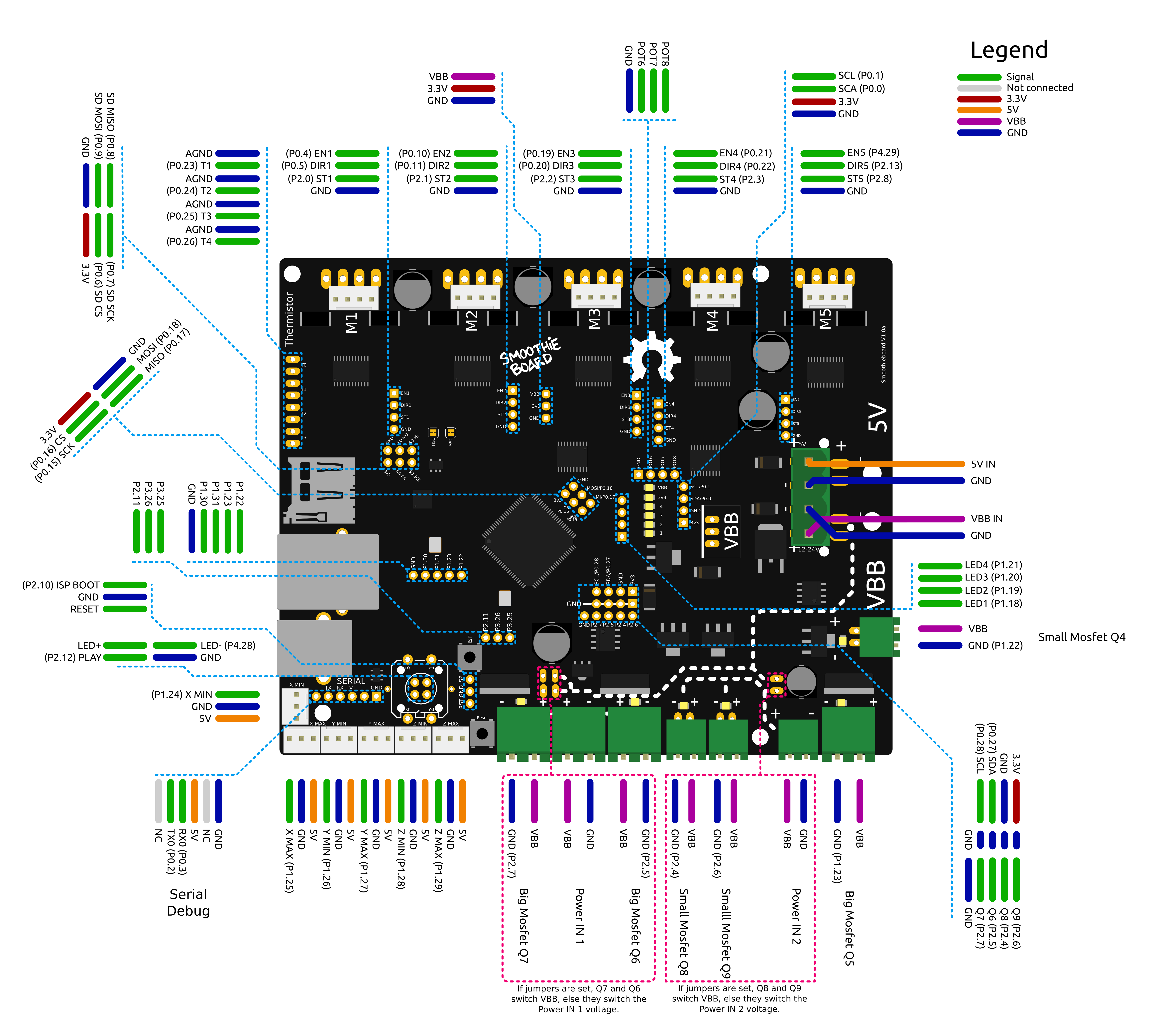
External Stepper Drivers
The logic pins that control the stepper drivers are broken out on all 5 axes to 1x4 pin headers found near each driver on the board. The 4 pins are EN, DIR, STP, and ground. These pins or their equivalents are found on most external stepper drivers. Many drivers call the STP (step) pin PUL (pulse). Some will call the DIR (direction) pin PHA (phase).
Most external drivers have both a + and - pin for each of EN, DIR, and STP. The simplest way to connect the external driver is to wire Smoothieboard GND to all 3 - pins, and the logic pins of Smoothieboard to the corresponding + pins. Note that Smoothie is 3.3V logic and each pin can only supply a maximum current of 4 mA, which is not usually a problem unless interfacing to very large, or very old external drivers which may need a little more.
[!TIP] While this example will show using the pins of one of the on-board drivers to control the external driver, you can use pretty much any free GPIO pin to control the step/direction/enable pins on your external driver.
All loadouts of Smoothieboard (3x, 4x, 5x) can control 5 external stepper drivers using these ports. The presence or absence of a built-in driver will not affect the external driver.
This shows control of an external driver using the pins on the positive side of the external driver’s input.

Please note, if your external driver requires 5V, that Smoothieboard only provides 3.3v on its output pins.
Two solutions to this: either use a level shifter or use the Smoothieboard’s pins as Open-Drain (i.e., linking to ground instead of linking to 3.3v, when closed), and wire accordingly.
For example:

Here, the 5V is taken from an endstop input’s positive terminal, taken to the 5V inputs on the external driver. The step/direction/enable pins on the Smoothieboard are taken to the GND inputs on the external driver.
In this case, you will also need to change those pins to be open-drain. To change a pin from being normal to being open-drain, you add a o lowercase “o” to the pin’s number. For example:
alpha_step_pin 2.0 # Pin for alpha stepper step signal
becomes
alpha_step_pin 2.0o # Pin for alpha stepper step signal
it’s also possible to invert a pin:
alpha_step_pin 2.0!o # Pin for alpha stepper step signal
[!NOTE] Reprap Discount has a nice external driver called the Silencio.
It does 1/128 microstepping, so using it with Smoothie makes a lot of sense since Smoothie can do higher step rates.
It comes with an adapter for pololu-type drivers for RAMPS-type boards. However, you can also simply wire it to Smoothie’s external driver connectors.
The only catch is: the pins are not in the same order in Smoothie and on the driver’s cable. (Note the colors maybe different on your cable)
Silencio cable color Black Green Red Blue Silencio connector order +5v Enable Direction Step Smoothie connector order Ground Step Direction Enable No big deal though, you simply need to swap the step and enable pins in the configuration file. Also DO NOT connect the Black wire to the 4th pin on Smoothie which is GND on Smoothie, it must be connected to a +5v pin elsewhere (e.g., on the endstops)
Additionally, you need to invert (by adding a
!to the pin number) the enable pin (that’s specific to the Silencio) The step pin does not need to be inverted.For example for your alpha driver, change:
alpha_step_pin      2.0       # Pin for alpha stepper step signal
alpha_dir_pin       0.5       # Pin for alpha stepper direction
alpha_en_pin        0.4       # Pin for alpha enable pin
to
alpha_step_pin      2.0       # Pin for alpha stepper step signal
alpha_dir_pin       0.5       # Pin for alpha stepper direction
alpha_en_pin        0.4!      # Pin for alpha enable pin
And just wire the Silencio connector to the Smoothieboard external driver connector
[!NOTE] There are more versions labeled TB6600 on the market, but they use different driver chips inside. First of all, you’ll need to know if the driver is ok with higher step rates (200 kHz), or you’ll have to tune
microseconds_per_step_pulseand/orbase_stepping_frequency.Since TB6600 uses 5V signals and Smoothie is 3.3V we should either use TTL converters or open-drain (as mentioned before). My setup uses open-drain with 5V taken from the board (signals are connected to “-“ pins, 5V is to all “+” pins).
The config is the following for alpha, but it’s the same for the rest:
# Stepper module pins (ports, and pin numbers, appending "!" to the number will invert a pin)
alpha_step_pin                               2.0!o              # Pin for alpha stepper step signal
alpha_dir_pin                                0.5!o              # Pin for alpha stepper direction
alpha_en_pin                                 0.4!o              # Pin for alpha enable pin
If you want to change the rotating direction, simply leave out the “!”:
alpha_dir_pin 0.5o # Pin for alpha stepper direction
Multiple drivers in parallel
If one of your axes requires more than one motor and driver, you can wire the control signals for one axis to multiple drivers, like so:
Solid State Relays
The big mosfets on the Smoothieboard can handle up to 12Amps. Sometimes that’s not enough. Say you want to control a big spindle, a gigantic heated bed, or a tesla coil.
Typical Solid State Relays (SSR) can handle up to 40Amps easily, sometimes more. AC ones can run 220V AC, and DC ones up to 60V DC (typically, look at the specs for yours).
To control your Solid State Relay (SSR), you will need one GPIO pin (use one of the free ones on the board ideally), and a connection to GND (plenty of those).
An SSR is essentially a big switch: you cut a wire, plug each end of the cut wire into its two terminals, and then you’ll be able to control whether or not those two ends of the wire connect or not. Simple as that.

You will need to connect GND on the Smoothieboard to the “-“ connection on the Input side of the SSR, and the GPIO pin on the Smoothieboard to the “+” connection on the Input side of the SSR. This example shows using P1.30
Then simply configure the module that will be using the SSR to use that pin, for example in the case of Switch:
switch.misc.enable                   true #
switch.misc.input_on_command         M42  #
switch.misc.input_off_command        M43  #
switch.misc.output_pin               2.4  # GPIO pin we connected to "+" on the SSR
switch.misc.output_type              digital        # just an on or off pin
In the case of TemperatureControl, where you use the SSR to control a heating element for example, there is a catch.
SSRs have a low maximum frequency they can be switched at. You need to specify that frequency or Smoothie will drive it way too fast. In this example, the maximum frequency is 20Hz.
So, you need to modify your module to both use the correct pin (the free GPIO you wired to the SSR), and to the correct frequency. Here are the two lines to change:
temperature_control.swimming_pool_heating.heater_pin               2.4
temperature_control.swimming_pool_heating.pwm_frequency            20
Another option, which turns the heaters on/off even less often, is to use bang-bang, where the state is only changed when temperature deviates too much from the set value:
temperature_control.bed.bang_bang            true            # set to true to use bang bang control rather than PID
temperature_control.bed.hysteresis           2.0             # set to the temperature in degrees C to use as hysteresis
                                                              # when using bang bang
Swapping stepper motor drivers
On some boards, you might want to swap two axes.
For example, you have a board that has two connectors on the Z axis, but you want to connect two motors to the Y axis (which has only one connector).
In that case, all you need to do is exchange the 3 pin definitions for these two axes.
For example:
beta_step_pin                                2.1              # Pin for beta stepper step signal
beta_dir_pin                                 0.11             # Pin for beta stepper direction
beta_en_pin                                  0.10             # Pin for beta enable

gamma_step_pin                               2.2              # Pin for gamma stepper step signal
gamma_dir_pin                                0.20             # Pin for gamma stepper direction
gamma_en_pin                                 0.19             # Pin for gamma enable
Becomes:
beta_step_pin                                2.2              # Pin for beta stepper step signal
beta_dir_pin                                 0.20             # Pin for beta stepper direction
beta_en_pin                                  0.19             # Pin for beta enable

gamma_step_pin                               2.1              # Pin for gamma stepper step signal
gamma_dir_pin                                0.11             # Pin for gamma stepper direction
gamma_en_pin                                 0.10             # Pin for gamma enable
Now your beta driver becomes your Z axis, and your gamma driver becomes your Y axis.
Please note that the current control parameters do not get swapped: alpha_current always controls the current for M1, no matter what you do to the step/direction pins.
Which pins are which
[!NOTE]

[!NOTE]
Also see the pin usage table

Notes:
- Do not use endstop inputs as outputs (for example to control a solid state relay), this will not work.
Protecting a power input with a fuse
A Fuse is a device which sacrifices itself (gets destroyed and stops letting electricity through) if the current passing through it is higher than a certain value.
As such, adding a fuse between your power supply and a power input on your Smoothieboard protects you against short circuits, overloading, mismatched loads, or any kind of device failure.
You need to choose a fuse with a value higher than your “normal” current for a given circuit. For example, if your heated bed consumes 10A, you want to have a 15A fuse protecting it, that way if everything is fine the fuse does not burn, but in case of a short circuit, it does.
Here is an example of a fuse protecting the mosfet power input:
 Note the fuse must have an adequate rating
Comments:
- Converted the external link to a Fuse to markdown format.
- Reworded the explanation of a fuse for clarity.
- Converted the image to markdown format and updated the path to match the new structure.
- Added a note about the fuse rating in italics for emphasis.