smoothieware-website-v1
Your guide to installing Smoothieboard in a Laser Cutting machine
![]()
A Laser Cutter is pretty much a CNC router with a weird and very very thin tool. As far as installing Smoothieboard in a machine goes, they are probably the simplest machine to set up. They can also be quite dangerous, so, be cautious.
This is a step-by-step guide to connecting your board to the various components of the laser cutter, configuring everything, from the beginning to actually cutting material.
This guide is a community effort, and this page is a Wiki. Please don’t hesitate to edit it to fix mistakes and add information, any help is very welcome.

On a typical laser cutter setup, installing a Smoothieboard will mean you do the following things:
- Read all of the guide before you start, best way to avoid mistakes
- Install some Software to talk to your board
- Install the Windows drivers if using that OS
- Connect your board via USB and practice talking to it
- Take a look at the configuration
- Upgrade your firmware to the latest version if you feel like it
- Wire your power supply and provide it with power
- Wire the power supply to Smoothieboard’s motor input
- Connect motors to the stepper motor driver outputs
- Edit your configuration to match your motors
- Test the motors, and admire your accomplishment for hours
- Connect Endstops to the endstop inputs
- Edit your configuration to match your endstops
- Test your endstops by homing the machine
- Connect your laser power supply and your Smoothieboard together
- Configure it so you can control the power supply’s output, and test
- Connect, configure and test any probes you may have
- Setup leveling if relevant
- Configure your CAM software and generate a G-code file
- Use your host software to send your new G-code file to the Smoothieboard
- Watch as the machine cuts using your new Smoothieboard system
- Be happy
This guide will walk through everything you need to accomplish to successfully perform these steps.
At the end of this guide, you should have a fully working machine.
Machine-specific guides
Some guides have been written (or are being written) for converting specific machines to Smoothie. You can find additional information using these:
- Blue box guide
- Another blue box guide
- Red box guide
- K40 wiring notes
- K40-S Conversion Index
- Johann’s K40 smoothie guide
- Don’s K40 guide
- Full Spectrum laser guide
USB Connectors

Smoothie uses USB-B
Unboxing
Your Smoothieboard comes with a micro SD card in the microSD slot.
The boards come pre-flashed. With a basic configuration file installed on the SD card, no preparation is needed before you can connect Smoothieboard to your computer and start interacting with it.
The first thing you might want to do before you start connecting your board is to look at our list of Software, and install a “host” program to talk to the board.
[!WARNING] Don’t have a Smoothieboard? If you don’t have a Smoothieboard but have or consider purchasing an MKS board, please make sure you read What’s wrong with MKS
Connecting via USB
A good first step is to connect your board to your computer to familiarize yourself with it. Connect a USB-B cable to the USB connector on the board, and to your computer.
SD card

Files on your Smoothieboard's SD card
A moment after connection, your computer will recognize the Smoothieboard as a USB Mass Storage Device (like a USB disk-drive or an SD card reader), showing you the files present on the SD card. Drivers are needed for Windows 7/8, while Linux and Mac OS X directly support the device, you can find those drivers here.
This allows you to add, copy, edit, or delete any file you’d like. Already present on the SD card is a file named “config”. This file contains all of the configuration options for your board and is read when you start or reset your board. You edit the configuration simply by editing this file in a Text Editor, saving it, and resetting the board. No need to recompile or flash the board.
[!SUCCESS] You can read more about configuring your Smoothieboard at Configuring Smoothie
[!NOTE] The SD card can also be used to flash a more recent version of the firmware to your board, while the pre-flashed firmware should work this is not always the case, see where to get the binary file and how to flash it via the SD card.
It can also be used to store and play G-Code files, see Player.
USB Mass Storage is not the only thing you get when you connect the board. The board also exposes a USB CDC Serial interface, allowing you to send G-Code and receive answers. (There is also a DFU interface for flashing firmwares but that’s mostly for developers).
The CDC (Serial) interface is the interface host programs like Pronterface use to allow you to interact with your machine. If you are already familiar with it, you can try connecting right now and get an answer from the board. If not, we explain it all later in this guide.
Connecting via the network
Network

Hope you have fewer cables than this
The other main communication interface present on the Smoothieboard, apart from the USB port, is the Ethernet port, which allows you to connect your board to your local Ethernet network, and talk to the board via TCP/IP.
This is the same kind of technology you would find on a network-connected 2D printer, for example.
It allows you to access a web interface the board serves, and control the machine via your browser.
It also allows you to connect some software that supports it (like Pronterface and Visicut) to your Smoothieboard via the network.
Network is disabled by default but is very easy to enable and configure.
It is also the recommended main method of communicating with your Smoothieboard.
You can find all the information you need about using the network interface here: Network interface
Updating your firmware
Now that you have your board, a very good idea before starting is to update your firmware to the latest version.
You do this by downloading the latest firmware.bin file, copying it onto the SD card, and resetting the SmoothieBoard.
Then, the new firmware will “flash” (you will see the LEDs on the board do a little “dance”), and you will then have the latest version.
This is particularly useful if you ever need to ask for help, as people helping you will be assuming you have the latest version.
You can find the file, and information on how to flash it, at Flashing Smoothie Firmware.
Migrating
If you are migrating from another firmware, here are guides to help you understand how some values from your old firmware match the values in your new Smoothie system:
Safety
Lasers will make you blind. In an instant. In the blink of an eye, quite literally.
[!DANGER] Never look into the beam or at any surface the beam might reflect off of. Never have the machine powered while the door is open.
You are responsible for your own safety.
Eyes cannot be replaced.
If the machine does not come with a switch on the door that turns the laser off when the door is open, this is stupid and dangerous. Please install that switch.
If you leave your machine alone even for a few minutes, this can happen to you:

They can burn your house, and they can burn your eyes, be careful.
Comments:
- Converted the callout to a markdown alert/callout.
- The image source was kept as is, assuming the path will be corrected during the website migration.
- The HTML div tags were kept for the centered text, as markdown does not support text alignment.
Warnings
Before you start wiring your machine’s elements to the board, there are several things you need to keep in mind and be careful about during all of the assembly.
Make sure you read this. Seriously. Not kidding. Do it. It’s important.
[!DANGER] Polarity
Note the inversion between the 5mm and 3.5mm connectors
Always make sure the polarity is correct when wiring in power inputs (coming from the Power Supply). Reversed polarity can damage or destroy all or part of your board. Polarity is indicated on the board itself by the + and - signs. Double check. On older versions of the board, markings are partially hidden by the connector, making it confusing. Rely on only the diagrams.
To check the polarity of your power source, attach your multimeter probes to the two wires of your power source respectively. If the voltmeter reading is positive it implies that the red probe is connected to the positive wire (+) and the black probe to the negative wire (-).
The main (labeled VBB) power input has a reverse polarity protection, however, it will not hold forever. As soon as you notice something is wrong, turn the power supply off and check again.

[!DANGER] Disconnecting
Never disconnect or connect stepper motors from the stepper motor drivers while the board is powered (i.e., when the Power Supply is turned on).
The drivers have very good protection against most possible problems and are very hard to destroy accidentally. But it is possible.
[!WARNING] Shorts
Be careful that nothing metallic ever touches the board while it is powered on. Falling screwdrivers, nuts and bolts can cause shorts and destroy the board. Check the board before powering it on. Do not press the reset button with anything metallic, as you could slip and cause a short, use a plastic screwdriver or the like.
[!WARNING] Use the right connector
Always check the schematic before connecting power sources (coming from the Power Supply) to the board. Connected to the wrong connector can destroy components. A common example of this problem is plugging a power input cable, into the connector for an output, or plugging the limit switches in backwards.
[!WARNING] Crimping
Make absolutely sure of your connections using crimps or screw terminals, from wires to any type of connector, are very careful and well done. Connections (to the stepper motors for example) lost while the machine is running can destroy your board.
[!DANGER] Markings
In the case of the VBB power input, be careful. If your board came with connectors pre-soldered, the 5mm connector is present, and the polarity of that connector is that of the large traces in the wiring diagram to the right (red is +, blue is -). On some boards, the marking on the boards may be hidden by the connector itself, so for VBB, do not rely on the markings on the board, but on the diagrams on this page. However, if you did not get your connectors soldered, and want to solder a 3.5mm connector instead of a 5mm connector, also note that the polarity is the opposite.
[!INFO] USB v Ethernet
USB can, in some setups, be subject to interference, which causes disconnections, and can ruin your work. This is very hard to prevent if it happens even in normal conditions. Ethernet, on the other hand, does not have this problem: save yourself the trouble, and use Ethernet right away. It’s very nice. See Network for information on how to set it up.
[!WARNING] Destroying your board
If you receive a bad board, you will get a replacement. But if you destroy your own board, your only options will be to fix it yourself (which can be quite difficult), or get a new one.
This is why it is very important you make sure you do not destroy your own board. Smoothieboard is reasonably protected, but there are still things that will destroy it. The general idea is: if a part of the board gets too much power, it will get destroyed. Here are some common mistake users do that cause the board to get too much power and die:
- Plugging 12-24v (motor power) into anything you are not supposed to. Like the 5V line, or an end-stop or thermistor input for example. Problems with the 5V or 3.3V power are not as much of a problem as the board is 5V-tolerant, so wrong connections and shorts should be okay as long as they do not last too long.
- Shorting 12-24v to anything else, which is essentially the same as plugging it into a place you are not supposed to (see above). This can happen by dropping a metal object onto the board, bad soldering, loose wires, un-protected wires, etc …
- Using an inductive load (like a motor, fan or solenoid) on a MOSFET, without a diode across (see Fan documentation).
The general idea here is: always make sure everything is clean, and double-check everything before turning the power on. You can not learn by making mistakes here, as mistakes will likely cost you your board.
Electrostatic discharge can also destroy your board : make sure you properly ground everything.
[!DANGER] Heater safety
If your machine contains any heating element and uses the temperature control module to control it, please make sure you read the section about implementing all safety measures here, and implement as many as you can. Fires will kill you if you don’t.
[!DANGER] Grounding
Make sure your machine’s case and electronics are properly grounded, also make sure your location’s electrical installation’s grounding is correctly done.
See for example:
[!WARNING] Environmental hazards
Be aware of your environment: it’s not just the machine itself.
- On a laser cutter, the machine vents large quantities of toxic smoke and gas, make sure it is very well evacuated to a place where no-one is breathing them
- On a CNC-mill, dusts, like wood dust for example, can be explosive if they come in contact with a flame, be careful and take measures to limit dust in the air
- On a 3D printer, the acetone used to clean things is very flammable, and the sprays used to increase bed adherence are explosive, store them adequately and be careful when using them
In particular, you are even more in danger if you are using your machine in a confined space, always be on the watch for safety issues.
For a good read about safety, you can refer to the RepRap Wiki documentation on the subject
To properly understand some of the safety instructions in this documentation, basic knowledge about electricity is required. See this page for a refresher on the basics.
Logic Power Inputs

There are different ways of providing logic power to your board.
Your board needs two sorts of power to work: 12-24V power to turn motors, heat hotends, etc., and 5V (or “logic”) power to power the microcontroller (the brain).
There are three ways to provide 5V power to the board:
- By plugging a USB cable in, USB cables provide 5V
- By soldering a voltage regulator to the board (and providing 12+24V, which the voltage regulator then turns into 5V)
- By providing 5V directly to the 5V power input (next to the VBB power input)
If you want to keep it simple, the easiest solution is just to connect your Smoothieboard to your computer via USB.
Note you can connect several different power supplies at the same time, with no issue at all. Smoothieboard has diodes on-board that will simply get the power from the one with the highest voltage, meaning you can even turn one off and the other will be used without a reset.
If voltage and current are strange concepts to you, it’s probably a good idea before you continue setting up your board, that you read this introduction.
The board’s logic circuits (5V line) typically consume up to 500mA current (what is standard for a USB port).
Main Power Input
Without power, your board can not do much. The board uses power to operate the control logic and to move stepper motors, and power heating elements, fans, and others.
How to choose a power supply unit (PSU)
Two power supplies are required, 5.0V and ‘bulk’ power (VBB).
5.0V supply
- Voltage (V): The 5.0V supply should be regulated to 5% tolerance (4.75V to 5.25V). This supply provides power for the control logic circuitry, and should be a good quality regulated power supply (which is inexpensive). Using a cheap buck regulator from a higher voltage is not recommended, as ever exceeding 5.5V on this supply may instantly and permanently damage the control logic on your Smoothieboard.
- Current (A): The 5.0V supply should be rated to supply at least 1A continuous current (or more). Typical load is roughly 0.5A.
VBB supply
- Voltage (V): VBB can be from 12 to 24V. While most of the components on the Smoothieboard are rated up to 32V, it is not recommended or supported to use that high of a voltage. 12V PSUs are more common, and generally cheaper. However, the higher the voltage, the higher performance you can get from your stepper motors. This is the reason some designers use 24V PSUs. However, be careful that with a 24V PSU, you will need 24V fans, and will need to reduce the PWM setting for your heating elements or (preferred, and safer) use 24V heating elements.
- Current (A): The total current required is the current for each stepper motor, plus the current for every peripheral on your machine Smoothieboard will control. This depends on your machine type. On a typical 3D printer, you can safely consider 10A to be sufficient for the heated bed, and 10A or a bit less for the rest of the loads. Go for a 17 to 20A PSU if you have a heated bed. 7A to 10 is probably enough if you do not have a heated bed (or if you are setting up a CNC mill or a laser cutter). If you bought your machine as a kit, a PSU with appropriate current is most probably provided (or one is recommended). If building your machine yourself by self-sourcing, the documentation for the machine model will also most probably recommend a current rating. A power supply that is able to supply more current than is needed is not a problem. Having not enough current to drive your hot-end, heater bed, or motors is a problem.
General Notes
Multiple-output power supplies are available. In some cases, a minimum load must be applied to the primary output before the secondary output will be regulated to within tolerances. For example, a dual 5.0V and 12V supply might regulate the 5.0V well at no-load conditions, but the 12V output may be low until power is drawn from the 5.0V supply.
EMI Filtering
Electromagnetic Interference (EMI): Digital logic and power circuitry (such as stepper motor drivers) switches currents and voltages on and off very rapidly. This produces EMI proportional to the voltage, current and rate of switching. EMI can be radiated (as radio waves) and/or conducted through the power line cord or other connections. EMI can interfere with (produce noise in or prevent proper operation of) other equipment, including sensors and motion encoder modules. To reduce these effects, an EMI filter module may be added to help reduce the conducted emissions. An EMI filter module may not strictly be needed, however it is often simpler to take protective measures from the start rather than e.g. searching for the cause of strange, intermittent behavior or coming back to failed 3D prints for months – and then put in an EMI filter module.
Fuses / Circuit Breakers
A typical US AC wall outlet provides 110V to 120V and is protected by a fuse or circuit breaker with a 15A or 20A rating. As (for example) a motor load such as a refrigerator or saw briefly draws a much higher starting current, in order to avoid ‘nuisance trips’ a 20A rating does not instantly remove power when that load is exceeded.
A VBB power supply rated (for example) 12V at 10A can provide up to 12V x 10A = 120W (Watts) of DC power. Power supplies are not 100% efficient, thus it will require 5% to 30% more than 120W of input power to produce 120W of output power. It is usually safe to assume at least 70% efficiency at full load (higher for more modern supplies), so the power supply will only need perhaps 1.5A at 120VAC input. A 1A, 5V supply will require much less than 1A at 120VAC input.
While the equipment can only use perhaps 2.5A, the AC wall outlet will provide at least 15A to 20A continuously without tripping the circuit breaker or blowing the fuse. It would be possible (though rare) for a fault condition that drew for example 10A at 120V = 1200W to occur, which would be a fire hazard, without tripping the breaker. If you wish to address this possibility, adding an additional fuse and/or circuit breaker with (for example) a 3A rating in line with the AC ‘hot’ wire will ensure that if there is a lot of excess power being drawn due to a circuit failure, then this fuse will blow or circuit breaker trip, and power will be removed. Too low a fuse or circuit breaker rating will result in ‘nuisance’ trips.
Setup
Make sure you use a Regulated Power Supply, make sure you connect the ground wire for the mains to the power supply, and if it has a fan, make sure it has sufficient space around it to let air flow and cool it appropriately.
To wire the power supply unit to mains (wall AC power), make sure you connect the right colored wires to the right connectors on the PSU. The 3 connectors are “live”, “neutral” and “ground”. Color changes from cable to cable. You can find charts for your specific country/cable on the internet, but the following colors are the most common:
| Standard | Load/live color | Neutral color | Earth color |
|---|---|---|---|
| US | Black | White | Green |
| Europe | Brown | Light blue | Yellow/Green |
Once the wires connected to the PSU, make sure none of your computers is doing something important (like a system upgrade). In case something goes wrong, plug the PSU into a power strip with an on/off button. Then turn that button ON. If your house loses power, you did something wrong. If an LED illuminates on the PSU, everything is fine: unplug the PSU and continue.
If you are new to wiring, please check our how to wire guide.
[!DANGER] NEVER manipulate mains (220/110V) power wires while they are plugged into the wall plug. Unpleasantness and/or death are common consequences of not respecting this rule.
[!DANGER] Ground your printer’s frame by connecting it to the Earth terminal on your power supply. In the (unlikely) event that a power supply wire comes undone and touches the printer’s frame, this will prevent you from getting an unpleasant and/or deadly shock.
Now that the PSU is getting mains power, your PSU is converting it into 12V or 24V DC (Direct Current) power. You need to connect wires from it to the Smoothieboard to provide power.
The most important thing for DC is to respect polarity: + goes to +, - goes to -. On the PSU, + terminals are indicated as +, V+, 12V+ or 24V+. Ground (-) terminals are indicated as -, V-, COM or GND.
On the Smoothieboard they are indicated simply as + and -.

By convention, black (sometimes brown) wires are used for ground, and red (sometimes orange, white or yellow) wires are used for power connections.
You may want to turn on the power supplies and test the output voltages before connecting them to the Smoothieboard (and turn them back off before connecting).
Once the wires are correctly connected, you can turn the PSU ON. If everything was done correctly, the red LED (marked VBB) on the Smoothieboard will light up brightly.
[!WARNING] If the VBB LED does not light up, immediately turn the PSU off. Check polarity, and check all the connections are strong and properly done. When you turn the PSU on, make sure you are ready to immediately turn it back off.
Now that the board has power, you can use that power to move things!
Emergency stop
It is recommended you setup an emergency stop button on your machine, so that in case of a problem, you can easily and quickly turn the machine off. For information on how to do this, please read EmergencyStop.
Stepper Motors
A bit of theory:
« A stepper motor (or step motor) is a brushless DC electric motor that divides a full rotation of the motor into a number of equal steps. The motor’s position can then be commanded to move and hold at one of these steps without any feedback sensor (an open-loop controller). » (Wikipedia)
Because they work by steps, and you can accurately control how many steps you move in each direction, stepper motors are a very practical way of moving things to a desired position. This makes them great for most CNC applications.
Smoothie comes with stepper motor drivers designed for bipolar stepper motors, with a maximum current rating of 2 Amps.
[!IMPORTANT] There is a very wide variety of stepper motors around. Bigger motors are generally more powerful. For a given size, motors will have different torques, max speeds, and different capacities to maintain torque as speed increases.
It is important you choose the right motor for your application. The most common mistake is to choose a high inductance motor. There are two main “families” of motors out there: high inductance motors are mostly designed for maintaining position and moving rarely (like on a telescope mount), and low inductance motors are designed for moving often, and at high speeds (like on a CNC mill or 3D printer).
If you use a high inductance stepper motor with a Smoothieboard (or any “CNC” stepper motor driver), not only will you get bad speed/torque performance, but when moving the stepper motor (or axis) by hand, very high voltage will be generated, which can destroy your stepper motor driver.
You can recognize a “high inductance” stepper motor by the fact that it’s rated inductance is high, in general higher than
10mHis bad. If your motor doesn’t tell you its inductance, rated voltage is also an indication: high inductance stepper motors usually have high rated voltages, a typical value being12V, where “CNC” steppers have voltage below 5V. This is not what you want, you want a low inductance stepper motor, with an inductance ideally below 10mH, and a rated voltage ideally below 5VThe reprap community defines a good stepper motor like this:
Ideal stepper is (for reprap printers and similar small CNC using microstepping drivers on 12-24v supply) NEMA17 size, rated 1.5A to 1.8A or less, 1-4ohm winding resistance, 3 to 8 mH, 62oz.in (0.44Nm, 4.5kg.cm) or more of torque, 1.8 or 0.9 degrees per step (200/400 steps/rev respectively), for example the kysan 1124090/42BYGH4803 or the rattm 17HS8401 or Wantai
 Be careful you get the coils right
Wiring
Direct wiring
Bipolar stepper motors have two poles (bi-polar). Each pole is connected to two wires. That’s 4 wires coming out of your stepper motor. These have to be connected to your Smoothieboard.
Each stepper motor driver on the Smoothieboard has 4 connections to that effect. (Stepper motor drivers are labeled M1, M2 etc…)
The tricky thing is often to find out which wires connect to which poles. If you just wire things at random, you have a chance it will work, but let’s be scientific about it. Several methods:
- Documentation: Look at your motor, find its part number. Then google it. If you are lucky, you will find a schematic or a data-sheet that will indicate which wire goes to which pole. Note the colours that correspond to each coil.
- Fingers: When the two wires for a given pole touch together, a closed circuit for that pole is created. This makes the stepper motor more difficult to turn. You can use that effect to discover the poles. Turn the stepper motor shaft, it should turn freely. Now take two wires, and make them touch. Turn the shaft again. If it shows resistance, is harder to turn, you found a pole. If it doesn’t, keep one wire, and try another one for the second one. Do this until you find a combination that shows resistance. Once you find the two wires for a given coil, the other two wires are simply the other coil. Note the colours that correspond to each coil.
- Multimeter: Configure your multimeter to read resistance. Then the method is the same as the previous one, take two wires at random, test them, except you know you find a coil when you measure electrical resistance between two wires. If you measure no contact, try another wire combination. Note the colours that correspond to each coil.
Now to connect the wires to the Smoothieboard. Let’s call one coil A, and the other coil B. It doesn’t matter which is which. Polarity also doesn’t matter, all it changes is the direction the motor turns, and you can change that in the configuration file. Now simply connect your two wires to the Smoothieboard’s 4 pins for that stepper motor driver as such: AABB or BBAA. Other combinations like ABBA or ABAB will not work.
 If you don’t get it right, it won’t work properly
Once your stepper motor is properly connected to your Smoothieboard, it is ready to be controlled.
 In this example, a stepper motor is connected to the M1 driver, and power is provided to VBB (the main power input).
External Stepper driver
If you want to use larger stepper motors than the Smoothieboard’s drivers can handle (2A max), you need to use external stepper drivers.
You can find detailed information on how to wire an external stepper motor driver to a Smoothieboard in the External driver appendix.
 They often have useful information on them
Configuring
Example configurations are available on GitHub.
You can also refer to the Configuration documentation.
Current
The first thing you have to do is tell the stepper motor drivers what is the current rating for your stepper motors is. To drive the stepper motor correctly, the driver has to know the motor’s current rating.
Each stepper motor model has a precise current rating. You can drive your stepper motor at a lower current, which will make it more silent, but also less powerful. But you cannot drive the motor at a higher current than it is rated at. This would cause overheating, and possibly skipped steps.
The rating is often written on your stepper motor’s label (see picture on the right). If it is not, you can get it by googling the stepper motor model number, or by contacting your seller or manufacturer.
Once you have the correct rating, you can set the corresponding parameter in the configuration file.
Smoothie has a funny way of naming stepper motor drivers. Instead of naming them X, Y or Z, because this makes no sense in non-cartesian robots like delta robots, we name the drivers using Greek letters so they are arm application agnostic:
| Label on the Smoothieboard | M1 | M2 | M3 | M4 | M5 |
|---|---|---|---|---|---|
| Axis in a Cartesian machine | X (left-right) | Y (front-back) | Z (up-down) | E0: First extruder | E1: Second extruder |
| Greek letter | α (alpha) | β (beta) | γ (gamma) | δ (delta) | ε (epsilon) |
| Current setting configuration option | alpha_current | beta_current | gamma_current | delta_current | epsilon_current |
Now, as described in the “Unboxing” paragraph, connect the board to your computer, open the “config” file with a text editor, and change the configuration value for each stepper motor driver to the correct value.
For example, if your alpha stepper motor has a current rating of 1.68A, edit the corresponding line to read:
alpha_current 1.68 # X stepper motor current
Do this for each stepper motor you have to connect to the board. (If you have a Cartesian robot, see which motor connects to which stepper driver in the array above. If you use another type of arm solution, see the specific documentation.)

Steps per millimeter
A stepper motor driver operates in steps. It moves a certain number of steps in one direction, then a certain number of steps in another. You think in millimeters. You want your machine to go to a certain position in millimeters, then another position in millimeters.
You need Smoothieboard to convert the millimeters you ask of it, into steps the stepper motor driver understands.
That conversion depends on your exact arm solution. The most common, and the simplest, is the Cartesian arm solution, and it is the one we will focus on here. Documentation for other arm solutions can be found separately.
In the case of a Cartesian arm solution, you simply convert a certain number of millimeters to a certain number of steps. That is the steps_per_millimeter configuration option that you have to set for each stepper motor.
To compute it, you must multiply a certain number of factors.
- The object you move moves a certain number of millimeters for each rotation of the stepper motor. (This depends on the characteristics of the belt/pulley, or lead-screw system you are using.)
- The stepper motor moves a certain number of full steps per rotation. That is usually 200. (But it can be 400.)
- Each step is divided by the stepper motor driver into a certain number of microsteps. It is that number, and not the number of full steps, that we want. Smoothieboard V1.1 always divides steps into 32 microsteps. (16 for older smoothieboards).
The formula is as follows:
steps per millimeter = ((full steps per rotation) x (microsteps per step)) / (millimeters per rotation)
To help you, there is an awesome calculator by the awesome Josef Prusa: http://calculator.josefprusa.cz/
Once you know the correct value for a given stepper motor driver, set it in the config file.:
alpha_steps_per_mm 80 # Steps per mm for alpha stepper
Do this for each stepper motor driver.
In the case of your extruder stepper motor, the principle is the same, but the value is extruder_steps_per_mm.
Here are two good videos about steps-per-millimeters:

Direction
It is now time to test your stepper motors. For this, you will need to use host software like Pronterface or the web interface.
Now connect to your Smoothieboard over the serial interface. Power your machine on by plugging the PSU into the wall.
Now you need to move an axis to make sure the stepper motor is turning in the right direction. In Pronterface, click near the yellow arrow marked “+X”.
Your X axis will move. If it moved to the right, great! Everything is fine, and you have nothing to change. If it moved to the left, you need to invert the direction of that axis.
You do this by editing the configuration file, and inverting the direction pin for that stepper motor driver:
alpha_dir_pin 0.5 # Pin for alpha stepper direction
Becomes:
alpha_dir_pin 0.5! # Pin for alpha stepper direction
This is for your axes. In the case of your extruder, the config value is extruder_dir_pin.
Save the config file, reset the Smoothieboard, connect again using Pronterface. Now the axis will move in the right direction.
Do this for each axis.
[!WARNING] If you have a moving bed in the Y axis for example, as opposed to a moving tool, be careful: what matters is the direction of the head relative to the bed, not the direction of the bed relative to the machine. It’s very common to get confused and invert your Y axis on moving bed machines (or not invert it when it should be). Basically, if an asymmetrical object looks like the model when it is printed, then your Y axis is correct, otherwise you need to change your configuration.

It’s essentially just a switch
Endstops
End-stops are small interrupters that you put at the end of each of your axes. When you boot your machine up, Smoothie has no way of knowing the position of each axis. When it starts a print, Smoothie moves the axis until it touches that interrupter, and when it is hit, it declares that that is position 0 for that axis. And does so for all axes.
This allows Smoothie to then precisely know where everything is relative to that initial position. It is quite convenient as it saves you the hassle of actually moving the machine into that position when you want to start a print. Automation is great.
However, end-stops are not necessary, you could do without them. They are just so convenient that most machines use them.
End-stops can also be used as limit switches which prevent the machine from attempting to move beyond the physical limits of the axis (by pausing/stopping movement when triggered), see the Endstops page for details about configuring Smoothie to use End Stops as limit switches.
[!NOTE] To make things as simple as possible: In Smoothie, endstops do three things:
- Homing (move til endstop is hit)
- Hard endstops (stop when endstop is hit, which is optional)
- Soft endstop (once homed, do not go further than a set position, which is also optional)
[!WARNING] Smoothie does not allow you to use a zprobe as an endstop. An endstop must be dedicated to being an endstop and cannot be used as a zprobe and vice versa. This does not mean ANY kind of feature is missing, you can still do everything you expect, this is just a subtility in vocabulary and in how configuration is organized, that new users are generally fine with, except if they come from another system which has a different paradigm.

There are 6 of them, two for each axis
Mechanical endstop wiring
This will concentrate on the most common type of end-stops: the mechanical ones. Other types exist like optical or hall-o sensors.
[!WARNING] There are plenty of fun and futuristic endstop types around: optical, laser, magnetic, force-sensitive, infrared, inductive, etc…
However, please note that the general feedback from the community, is that most of those are either less precise, less repeatable, or much more difficult to get to “work right”, compared to the classical “mechanical” endstop.
The mechanical endstop is actually likely the most precise, repeatable and easy to get to work option you have at your disposal. Just because these other options exist and have been explored by the community, does not mean they are better.
You might happen have a good reason to use a fancy endstop, but if you don’t, it’s likely a good idea to stick with a mechanical one.
Mechanical end-stops are simple interrupters: when not pressed, they do not let the current pass, when pressed, they let the current pass. By connecting a digital input pin on the Smoothieboard to the interrupter, and connecting the other side of the interrupter to Ground, the Smoothieboard can read whether or not it is connected to Ground, and therefore whether or not the end-stop is pressed.
Most mechanical end-stops have 3 connection points, to which you have to attach your wires:
- C: Common
- NO: Normally Open, meaning it is not connected to C when the interrupter is not pressed, and connected to C when the interrupter is pressed.
- NC: Normally Closed, meaning it is connected to C when the interrupter is not pressed, and not connected to C when the interrupter is pressed.

You want to connect the Signal (green in the schematic) and Ground (blue in the schematic) pins for the end-stop on the Smoothieboard, to the C and NC connection points on the end-stop.
[!NOTE] For each endstop, we connect C to Signal and NC to Ground because this means the digital input pin (endstop connector) will be connected to Ground in its normal state and cut from Ground when the button is pressed. This approach is less prone to noise than the reverse. See here for more information.
Another positive effect of this approach is, that if a wire breaks for some reason you get the same signal as if the endstop is pressed. That makes sure that even with a damaged wire you are not able to overrun the endstop.
[!DANGER] Make absolutely sure that you do not connect VCC (red) and GND (blue) to a mechanical (microswitch) endstop! Depending on your wiring this may fry your smoothieboard instantly or when the switch gets pressed. There is certain wiring where this won’t happen when you switch the signal between VCC and GND, but if you’re not careful enough you will damage your board.
You want to connect your X end-stop to the X min pins, Y end-stop to the Y min pins, and Z end-stop to the Z min pins.
Powered endstops wiring
Mechanical endstops are simple switches, they simply let a signal pass through, or not, allowing us to detect their status with an endstop input. It has no intelligence of its own.
There are more sophisticated endstops. Those are “powered endstops”, for example: Hall-O (magnetic) or optical endstops.
The only difference between a mechanical endstop and those powered endstops is that they require being provided with 5V power.
This means that where for a mechanical endstop you connect the Signal and GND pins, for a powered endstop, you connect the Signal, GND and 5V pins.
Other than this, it works exactly the same as a mechanical endstop: The Signal pin receives something different depending on whether the endstop is triggered or not.
Different powered endstops have different behaviors:
Some connect Signal to Ground when triggered, and Signal to 5V when not triggered.
Others connect Signal to 5V when triggered, and Signal to Ground when not triggered.
To know exactly what your endstop does, see its documentation.
If once wired, your endstop reports the opposite of what it should via the M119 command (1 when triggered/pushed, and 0 when not triggered), see the “Testing” section.
Some endstops might require removing their “pull-up” configuration, in this case, change:
alpha_min_endstop 1.28^
To:
alpha_min_endstop 1.28
And if you need it to be a pull-down, change it to:
alpha_min_endstop 1.28v
In some very rare cases, the endstop reading circuit on the Smoothieboard will not be adequate for your endstop type. In this case, you should use a “free” GPIO pin on the Smoothieboard that nothing else uses to connect your endstop to.
See Pinout to find adequate pins.
Testing
The default configuration most probably already has everything you need: the pins are already correct and the default speeds are reasonable.
Once they are wired, you can test your end-stops.
To do this, reset your Smoothieboard, then connect to it using host software like Pronterface or the web interface.
Now connect to your Smoothieboard over the serial interface. Power your machine on by plugging the PSU into the wall.
Now in Pronterface, home one axis by clicking the small “home” icon for that axis. Begin with X, then Y, then Z.
If your axis moves until it hits the end-stop, then stops when it hits it, moves a small distance back, then goes a bit slower back to the end-stop and stops, that end-stop is working fine.
On the other hand, if the axis moves a small distance in the wrong direction, then stops, you have a problem: your Smoothieboard always reads the end-stop as being pressed. So when you ask it to move until the end-stop is hit, it reads it immediately as pressed and stops there.
Another problem can be that the axis moves and never stops, even after the end-stop is physically hit. This means your Smoothieboard actually never reads the end-stop as being pressed.
There is a command that allows you to debug this kind of situation: in Pronterface, enter the “M119” G-code.
Smoothie will answer with the status of each endstop like this:
X min:1 Y min:0 Z min:0
This means: X endstop is pressed, Y and Z endstops are not pressed.
Use a combination of this command, and manually pressing end-stop, to determine what is going on.
If an end-stop is read as always pressed, or never pressed, even when you press or release it, then you probably have a wiring problem, check everything.
If an endstop is read as pressed when it is not, and not pressed when it is, then your end-stop is inverted.
You can fix that situation by inverting the digital input pin in your configuration file. For example if your X min endstop pin is inverted, change:
alpha_min_endstop 1.28^
To:
alpha_min_endstop 1.28^!
Here is the exact mapping of pin names to inputs on the Smoothieboard:
| Endstop | X MIN | X MAX | Y MIN | Y MAX | Z MIN | Z MAX |
|---|---|---|---|---|---|---|
| Config value | alpha_min | alpha_max | beta_min | beta_max | gamma_min | gamma_max |
| Pin name | 1.24 | 1.25 | 1.26 | 1.27 | 1.28 | 1.29 |
More information can be found here.
 They look nice but they are dangerous
Laser control

They use very high voltages and are dangerous
Laser control
The Laser module is the part of Smoothie that allows you to control laser cutters.
In general, laser cutters use a CO2 tube to generate the laser beam used for cutting and engraving.
Those tubes contain CO2 gas, and a high-voltage Power Supply Unit is used to pass electricity through the gas, generating the beam.
Using G-code, you tell Smoothie where to move and when to cut. Smoothie moves the motors, and the Laser module talks to the laser power supply to tell it when to turn off and on, and using how much power.
[!DANGER] Be very careful with the laser tube side of your Power Supply: voltages there are commonly around 40,000 volts, making it very dangerous.
If you are not qualified to handle this kind of voltage, please contact a professional.
Always make sure everything is powered down before manipulating anything.
[!SUCCESS] For laser cutters, you will get some extra features (in particular nice laser-specific screen information on panels) if you use the “cnc” version of the firmware. Though the normal (edge) version will work fine. See flashing the firmware and choose the file called
firmware-cnc.bin.
Wiring
In order to control the power of the laser tube, the laser PSU reads a PWM signal as its input.
Please look at the datasheet for your PSU to know which connection that signal is wired to.
From the Smoothieboard, you need to connect:
- One GND pin to the Ground connection on the PSU
- One of Smoothie’s PWM pins to the PWM input on the PSU
Both Ground pins are easy to find, and the PSU input you find in the manual/datasheet, now all you need is to find a PWM pin on the Smoothieboard.
There are 6 of them, but 4 of them are used for the step pins for stepper motor drivers.
Those for alpha and beta you won’t be able to use as you use those drivers to control the X and Y axes.
Depending on whether you have a Z axis, your gamma axis step pin could be used. It is labelled ST3, on the JP12 header, near the M3 stepper motor driver.
You probably do not use your delta (M4) stepper motor driver on a laser cutter, so that pin can also be used, it is labelled ST4 on the JP15 header near the M4 stepper motor driver.
The other two are found near the microcontroller and the MOSFETS, on the JP33 header, and are labelled PWM0 and PWM1.
Choose which you will use, all have a GND header close-by (all are unlabelled) to make it convenient for wiring.
Now you need to find which GPIO pin/port number corresponds to the PWM pin you chose, so you can tell Smoothie which you’ll be using in the configuration file.
| Pin number for configuration | Label on the board | Comment |
|---|---|---|
| 2.2 | STP3 | Only if you are not using a Z axis/the gamma driver. Make sure you set gamma_step_pin to the “nc” value. The unlabelled pin in JP12 is GND. |
| 2.3 | STP4 | Only if you are not using the delta driver. Make sure you set delta_step_pin to the “nc” value. The unlabelled pin in JP15 is GND. |
| 2.4 | PWM0 | Only if you are not using the first small MOSFET (X8). All pins of JP10 are GND. |
| 2.5 | PWM1 | Only if you are not using the second big MOSFET (X15). All pins of JP10 are GND. |
Now that the PSU is wired to the Smoothieboard and that you know which pin you are using for control, you can change the configuration file to setup laser control
Configuration
You now need to edit the “config” file on the SD card (the default configuration file already contains example laser lines so you may only need to edit/enable those) to add or setup the laser part as follows:
# Laser module configuration
laser_module_enable                          true             # Whether to activate the laser module at all. All configuration is
                                                              # ignored if false.
laser_module_pwm_pin                         2.5              # this pin will be PWMed to control the laser. Only P2.0 - P2.5
                                                              # can be used since laser requires hardware PWM
#laser_module_maximum_power                  0.8              # this is the maximum duty cycle that will be applied to the laser
#laser_module_minimum_power                  0.0              # this duty cycle will be used for travel moves to keep the laser
                                                              # active without actually burning
#laser_module_pwm_period                     20               # this sets the pwm frequency as the period in microseconds
If needed, replace the 2.5 value for laser_module_pwm_pin with the pin you chose in the wiring section.
Save the file, reset the board, you are now ready for laser testing.
All options
Laser Module Configuration
The following table outlines the configuration options for the laser module in Smoothieware:
| Option | Default Value | Description |
|---|---|---|
laser_module_enable |
true |
Whether to activate the laser module at all. All configuration is ignored if false. The laser module is used for laser cutting using a laser diode or CO2 laser tube. |
laser_module_pwm_pin |
2.5 |
This pin will control the laser. Pulse width will be modulated to vary power output (PWM). Note: PWM is available only on pins 2.0 to 2.5, 1.18, 1.20, 1.21, 1.23, 1.24, 1.26, 3.25 and 3.26. |
laser_module_ttl_pin |
1.30 |
This pin turns on when the laser turns on, and off when the laser turns off. |
laser_module_maximum_power |
0.8 |
This is the maximum duty cycle that will be applied to the laser. Value is from 0 to 1. |
laser_module_minimum_power |
0.0 |
This duty cycle will be used for travel moves to keep the laser active without actually burning. Useful for some diode setups. Value is from 0 to 1. |
laser_module_pwm_period |
20 |
PWM frequency expressed as the period in microseconds. |
laser_module_proportional_power |
true |
Whether the laser power should be proportional to the current speed, so as speed of movement ramps up (and down), laser power is proportionally adjusted, so that the amount of laser power/quantity of photons for a given distance/area is always constant, even if speed has to increase/decrease progressively. This is true by default, but in some situations you might want to disable this feature. |
Example setup
Exactly how to wire your Smoothieboard to control your laser power supply is going to depend on the PSU itself, so we highly recommend you read the documentation for yours.
This is an example that should be the most common case, which you are most likely to encounter: the Chinese power supply with “H L P G IN 5V” connections. In this example a RECI power supply but this should apply to most Chinese power supplies.
The basic idea is this: pin 1.23 (hardware PWM-capable) is configured as open-drain and inverted (1.23o!), then connected to the L (Low) TTL input on the power supply. Ground from the Smoothieboard is connected to ground on the Power Supply.
The rest is specific to the supply: P is connected to G through the door switch and water protect circuits, this ensures that if the door is opened or the water chiller turns off, the laser is turned off. Finally, IN is connected to 5V, setting the laser power at full (but it can still be modulated by Smoothie’s PWM).
Here you could in theory replace the jumper by a potentiometer, allowing you to manually adjust the maximum laser power.
The wiring looks like this:

You then also need to configure the laser module accordingly:
# Laser module configuration
laser_module_enable                          true             # Whether to activate the laser module at all. All configuration is
                                                              # ignored if false.
laser_module_pwm_pin                         1.23o!           # this pin will be PWMed to control the laser. Only P2.0 - P2.5
                                                              # can be used since laser requires hardware PWM
Note on K40
The wiring above probably won’t work on a K40, which are fairly weird machines (cheap comes at a cost).
For K40, see the several build logs linked to at the top of this page. In particular, you’ll likely need to increase the pwm frequency, and wiring might need to be different depending on your model.
Testing
[!DANGER] Make sure your laser cutter enclosure is closed and that everything is safe.
Wear laser protection googles, even if the machine is properly closed.
Make sure your machine has a proper enclosure, and a switch on the door that turns it off when the door is opened.
Do not do anything until this is properly setup.
Lasers can make you blind. And bionic eyes are not there just yet.
Here is how Smoothie laser control works: G0 and G1 are exactly the same command, they take positional parameters (X10 Y5 Z3 for example) and move the tool to that position.
The only difference is that when using G0 the laser stays off, and when using G1 the laser is on, only during movement.
To test, try moving your laser with G0 and try moving it with G1:
G0 X10 F300
G1 X20 F300
You can set the power for the laser by using the S parameter. Values go from 0 (0%) to 1 (100%).
For example:
G1 X10 F300 S0.2
Supported G-codes
The following G-codes are supported by the Laser module:
G0: Move without activating the laserG1/G2/G3: Move with the laser activatedS: The S parameter sets the current power of the laser, when it is activated, from 0 (0%) to 1 (100%).M221 Snnnglobally scales the laser power provided by G1 by nnn percent. So M221 S75 will scale the laser power to 75%.M221 Rxxx: Set the PWM frequency to xxx Hz (Hertz). This specifies frequency, and not period, be aware and careful.M221 P1: Temporarily disable proportional laser power (as per thelaser_module_proportional_powerconfiguration option, see its description for more details). This is not saved by the M500 command.
Supported commands
The following commands are available for testing (prepend @ in pronterface or M1000 in other hosts)
fire nnnwhere nnn is 0-100 percentage of power (example fire 10 will turn on laser at 10%)fire offturn off the test fire and return to automatic mode.
[!NOTE] If you want to learn more about this module, or are curious how it works, Smoothie is Open-Source and you can simply go look at the code, here.
Probing
Smoothie allows you to use a probe to do a variety of things:
- Calibrate machine geometry, for example for delta machines
- Automatically level un-even or non-level surfaces, using either grid or three-point methods
- Automatically find the distance between the tool and either the workpiece or the build surface
- Automatically detect tool lengths
To learn more about probing with Smoothie, read the zprobe module documentation.
Panel
A panel is the combination of a screen, and some kind of input method, attached to the machine, that allows you to easily do things like move the carriage, start a file, monitor its status, etc.
In order to use a panel with a Smoothieboard, you need to wire it to the board, and to modify the configuration file so the board knows it’s talking to a panel.
There are different types of panels supported by Smoothieboard. To learn how to wire and configure for your specific panel, please read the Panel page.
Appendixes
Printing, milling or cutting from the SD card
Printing, milling or cutting from the SD card on Smoothieboard is easy. First, you transfer your gcode files to the card. You can do this by moving the SD card to your computer and copying the files to it or simply copy the files to the card when it mounts on your desktop. If it isn’t mounting automatically, you are probably running Linux and have automount disabled. You can change that or manually mount it. The other option is to use the built-in Web Server if you have installed the RJ45 connector and an ethernet connection to the board. You can upload files to the SD card with this convenient Web interface.
Now, with your gcode files on the SD card, there are a few options to run it from there:
[!NOTE] Serial terminal You can use a serial port terminal application like CoolTerm (it supports OSX, Windows, Linux) or Cutecom (OSX and Linux). Once connected, enter
helpto get a list of supported console commands.If you use Pronterface with your 3D printer, you can use its built-in serial terminal feature - just prefix serial commands with an “@”. So, once connected to smoothie send
@helpand it will list all of the available commands.You can find more information about using the
playcommand here.You can also use the
M24G-code to play files from the SD card, see Supported G-codes.
[!NOTE] Web interface Another option is to use the Web interface mentioned above.
[!NOTE] Panel If you have a panel (like the RepRapDiscount GLCD) you can use the panel menus to run/pause/stop printing your gcode files.
Wiring
How well your machine is wired is going to determine how long it lives and how resistant it is to breakage.
We have a great guide on different techniques and recommendations, please read the how to wire page.
Crimping connectors
If your Smoothieboard came with connectors, you got connector casings, and crimps. You will need to attach your crimps to your cables, and then insert the crimps into the connector casings.
This tutorial is a good read about crimping properly.
[!WARNING] Please be careful and patient, if you have never done it before you will probably fail a few times before getting the hang of it. Also be careful to insert the crimp into your connector the right way around.
Soldering connectors
Please read this comic before soldering anything.
Using two steppers motor on a single driver
Stepper motor drivers on Smoothieboard can handle up to 2Amps per driver.
If you want to control two separate motors with a single driver ( for example you have two stepper motors for your Y axis like on a Shapeoko, or two stepper motors for your Z axis like on a Reprap Prusa i3 ) and have both motors move simultaneously, you have two options.
If the total of the current used by your motors is more than 2Amps ( for example two 1.5Amps motors are 3Amps ), you can not wire them together on a single driver, and you need to look at doubling drivers just below.
However, if your total current is less than 2Amps, you can wire both motors in parallel to a single driver.
To do so, find for each stepper motor, which wires match which coils, and wire the same coils into the stepper motor connections on the Smoothieboard ( two wires per connection, one from each motor, for each pin ).
If when you test it, the two motors turn in reverse, you need to reverse one of the coils of one of the stepper motors, and they will start turning in the same direction.
You also need to set a current value for that driver that matches the total current your two motors will be using. For example if the motors are each 0.8Amps, your total is 1.6Amps and you need to set for that specific driver ( here gamma driver is shown ) :
gamma_current 1.6
Doubling stepper motor drivers
If you need to drive two motors with a single axis, but the total current used for the motors is more than 2Amps ( for example two 1.5Amps motors add up to 3Amps ), you can not wire the steppers in parallel to a single driver and have it control both motors at the same time like described above.
This is the case for example for the Y axis of Shapeoko machines.
In this case, you will need to use one driver for each of your motors. This means you need a Smoothieboard with one more stepper motor driver than you have axes. If you have 3 axes and need to double one, you will need a 4X or a 5X Smoothieboard.
To enslave a driver to another, you will need to connect the control pins for both drivers together.
For example if you want the epsilon ( M5 ) driver to be the slave to the gamma ( M3 ) driver you will need to connect:
- EN3 to EN5
- ST3 to ST5
- DIR3 to DIR5
The connectors for this can be found close to the stepper motor drivers, and are labelled.
Finally you need to do two things in your configuration file:
First, set the current value for both drivers. For example if you are using gamma and epsilon set:
gamma_current       1.5
epsilon_current      1.5
Then, you need to make sure that none of the step, dir and enable configuration values for your slave stepper motor driver, are present in the configuration file.
For example if you are using gamma as a slave, make sure that none of the following values are present in the configuration file:
gamma_step_pin
gamma_dir_pin
gamma_en_pin
If they are, remove them. And be careful, for the delta driver, if you started from the 3D printer configuration file, they are not referred to as delta_xxx_pin but as extruder_xxx_pin, if they are present you must remove them all.
Only remove the lines for the slave driver.
External Stepper Drivers
The logic pins that control the stepper drivers are broken out on all 5 axes to 1x4 pin headers found near each driver on the board. The 4 pins are EN, DIR, STP, and ground. These pins or their equivalents are found on most external stepper drivers. Many drivers call the STP (step) pin PUL (pulse). Some will call the DIR (direction) pin PHA (phase).
Most external drivers have both a + and - pin for each of EN, DIR, and STP. The simplest way to connect the external driver is to wire Smoothieboard GND to all 3 - pins, and the logic pins of Smoothieboard to the corresponding + pins. Note that Smoothie is 3.3V logic and each pin can only supply a maximum current of 4 mA, which is not usually a problem unless interfacing to very large, or very old external drivers which may need a little more.
[!TIP] While this example will show using the pins of one of the on-board drivers to control the external driver, you can use pretty much any free GPIO pin to control the step/direction/enable pins on your external driver.
All loadouts of Smoothieboard (3x, 4x, 5x) can control 5 external stepper drivers using these ports. The presence or absence of a built-in driver will not affect the external driver.
This shows control of an external driver using the pins on the positive side of the external driver’s input.

Please note, if your external driver requires 5V, that Smoothieboard only provides 3.3v on its output pins.
Two solutions to this: either use a level shifter or use the Smoothieboard’s pins as Open-Drain (i.e., linking to ground instead of linking to 3.3v, when closed), and wire accordingly.
For example:

Here, the 5V is taken from an endstop input’s positive terminal, taken to the 5V inputs on the external driver. The step/direction/enable pins on the Smoothieboard are taken to the GND inputs on the external driver.
In this case, you will also need to change those pins to be open-drain. To change a pin from being normal to being open-drain, you add a o lowercase “o” to the pin’s number. For example:
alpha_step_pin 2.0 # Pin for alpha stepper step signal
becomes
alpha_step_pin 2.0o # Pin for alpha stepper step signal
it’s also possible to invert a pin:
alpha_step_pin 2.0!o # Pin for alpha stepper step signal
[!NOTE] Reprap Discount has a nice external driver called the Silencio.
It does 1/128 microstepping, so using it with Smoothie makes a lot of sense since Smoothie can do higher step rates.
It comes with an adapter for pololu-type drivers for RAMPS-type boards. However, you can also simply wire it to Smoothie’s external driver connectors.
The only catch is: the pins are not in the same order in Smoothie and on the driver’s cable. (Note the colors maybe different on your cable)
Silencio cable color Black Green Red Blue Silencio connector order +5v Enable Direction Step Smoothie connector order Ground Step Direction Enable No big deal though, you simply need to swap the step and enable pins in the configuration file. Also DO NOT connect the Black wire to the 4th pin on Smoothie which is GND on Smoothie, it must be connected to a +5v pin elsewhere (e.g., on the endstops)
Additionally, you need to invert (by adding a
!to the pin number) the enable pin (that’s specific to the Silencio) The step pin does not need to be inverted.For example for your alpha driver, change:
alpha_step_pin      2.0       # Pin for alpha stepper step signal
alpha_dir_pin       0.5       # Pin for alpha stepper direction
alpha_en_pin        0.4       # Pin for alpha enable pin
to
alpha_step_pin      2.0       # Pin for alpha stepper step signal
alpha_dir_pin       0.5       # Pin for alpha stepper direction
alpha_en_pin        0.4!      # Pin for alpha enable pin
And just wire the Silencio connector to the Smoothieboard external driver connector
[!NOTE] There are more versions labeled TB6600 on the market, but they use different driver chips inside. First of all, you’ll need to know if the driver is ok with higher step rates (200 kHz), or you’ll have to tune
microseconds_per_step_pulseand/orbase_stepping_frequency.Since TB6600 uses 5V signals and Smoothie is 3.3V we should either use TTL converters or open-drain (as mentioned before). My setup uses open-drain with 5V taken from the board (signals are connected to “-“ pins, 5V is to all “+” pins).
The config is the following for alpha, but it’s the same for the rest:
# Stepper module pins (ports, and pin numbers, appending "!" to the number will invert a pin)
alpha_step_pin                               2.0!o              # Pin for alpha stepper step signal
alpha_dir_pin                                0.5!o              # Pin for alpha stepper direction
alpha_en_pin                                 0.4!o              # Pin for alpha enable pin
If you want to change the rotating direction, simply leave out the “!”:
alpha_dir_pin 0.5o # Pin for alpha stepper direction
Multiple drivers in parallel
If one of your axes requires more than one motor and driver, you can wire the control signals for one axis to multiple drivers, like so:

Solid State Relays
The big mosfets on the Smoothieboard can handle up to 12Amps. Sometimes that’s not enough. Say you want to control a big spindle, a gigantic heated bed, or a tesla coil.
Typical Solid State Relays (SSR) can handle up to 40Amps easily, sometimes more. AC ones can run 220V AC, and DC ones up to 60V DC (typically, look at the specs for yours).
To control your Solid State Relay (SSR), you will need one GPIO pin (use one of the free ones on the board ideally), and a connection to GND (plenty of those).
An SSR is essentially a big switch: you cut a wire, plug each end of the cut wire into its two terminals, and then you’ll be able to control whether or not those two ends of the wire connect or not. Simple as that.

You will need to connect GND on the Smoothieboard to the “-“ connection on the Input side of the SSR, and the GPIO pin on the Smoothieboard to the “+” connection on the Input side of the SSR. This example shows using P1.30
Then simply configure the module that will be using the SSR to use that pin, for example in the case of Switch:
switch.misc.enable                   true #
switch.misc.input_on_command         M42  #
switch.misc.input_off_command        M43  #
switch.misc.output_pin               2.4  # GPIO pin we connected to "+" on the SSR
switch.misc.output_type              digital        # just an on or off pin
In the case of TemperatureControl, where you use the SSR to control a heating element for example, there is a catch.
SSRs have a low maximum frequency they can be switched at. You need to specify that frequency or Smoothie will drive it way too fast. In this example, the maximum frequency is 20Hz.
So, you need to modify your module to both use the correct pin (the free GPIO you wired to the SSR), and to the correct frequency. Here are the two lines to change:
temperature_control.swimming_pool_heating.heater_pin               2.4
temperature_control.swimming_pool_heating.pwm_frequency            20
Another option, which turns the heaters on/off even less often, is to use bang-bang, where the state is only changed when temperature deviates too much from the set value:
temperature_control.bed.bang_bang            true            # set to true to use bang bang control rather than PID
temperature_control.bed.hysteresis           2.0             # set to the temperature in degrees C to use as hysteresis
                                                              # when using bang bang
Swapping stepper motor drivers
On some boards, you might want to swap two axes.
For example, you have a board that has two connectors on the Z axis, but you want to connect two motors to the Y axis (which has only one connector).
In that case, all you need to do is exchange the 3 pin definitions for these two axes.
For example:
beta_step_pin                                2.1              # Pin for beta stepper step signal
beta_dir_pin                                 0.11             # Pin for beta stepper direction
beta_en_pin                                  0.10             # Pin for beta enable

gamma_step_pin                               2.2              # Pin for gamma stepper step signal
gamma_dir_pin                                0.20             # Pin for gamma stepper direction
gamma_en_pin                                 0.19             # Pin for gamma enable
Becomes:
beta_step_pin                                2.2              # Pin for beta stepper step signal
beta_dir_pin                                 0.20             # Pin for beta stepper direction
beta_en_pin                                  0.19             # Pin for beta enable

gamma_step_pin                               2.1              # Pin for gamma stepper step signal
gamma_dir_pin                                0.11             # Pin for gamma stepper direction
gamma_en_pin                                 0.10             # Pin for gamma enable
Now your beta driver becomes your Z axis, and your gamma driver becomes your Y axis.
Please note that the current control parameters do not get swapped: alpha_current always controls the current for M1, no matter what you do to the step/direction pins.
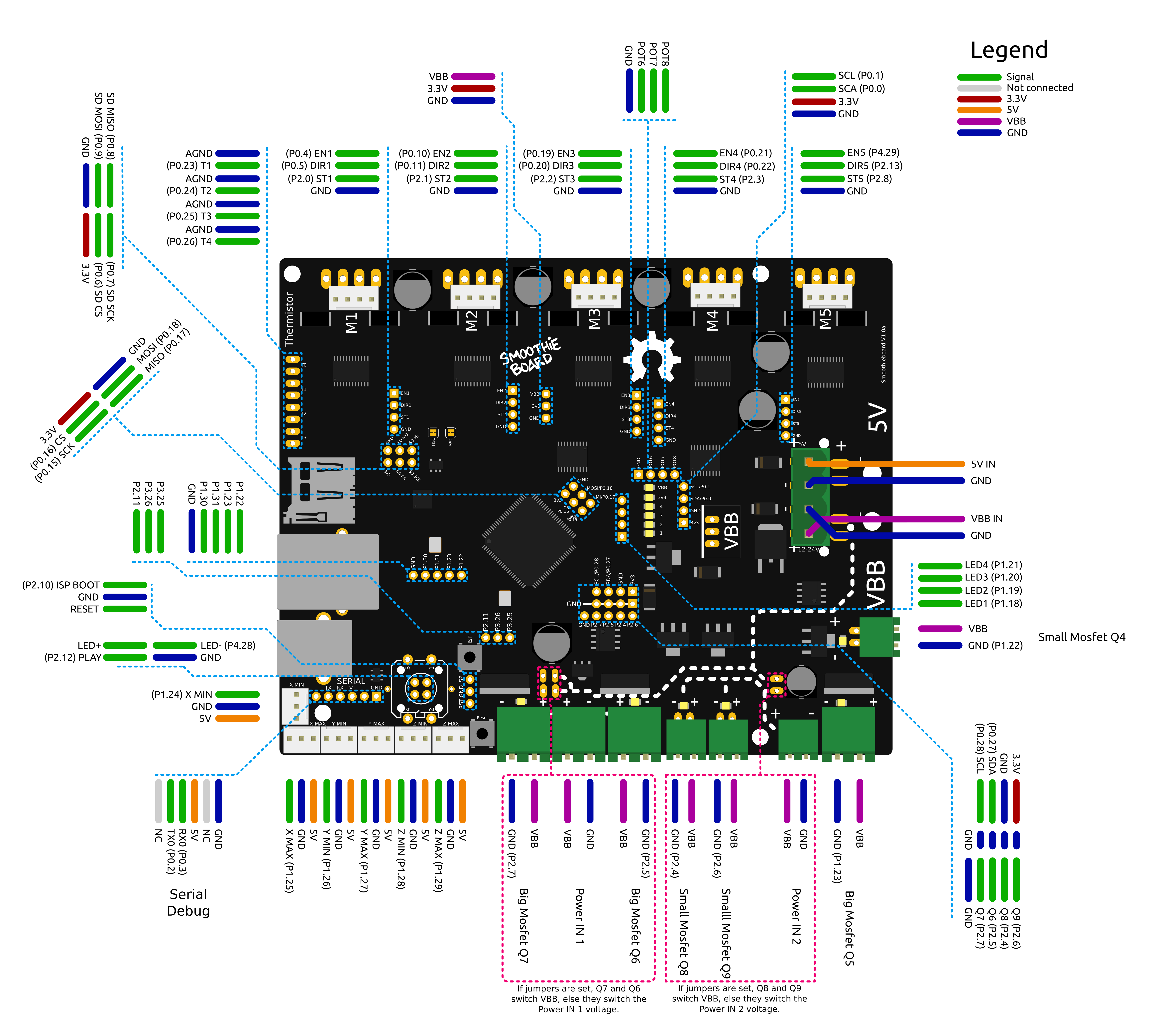
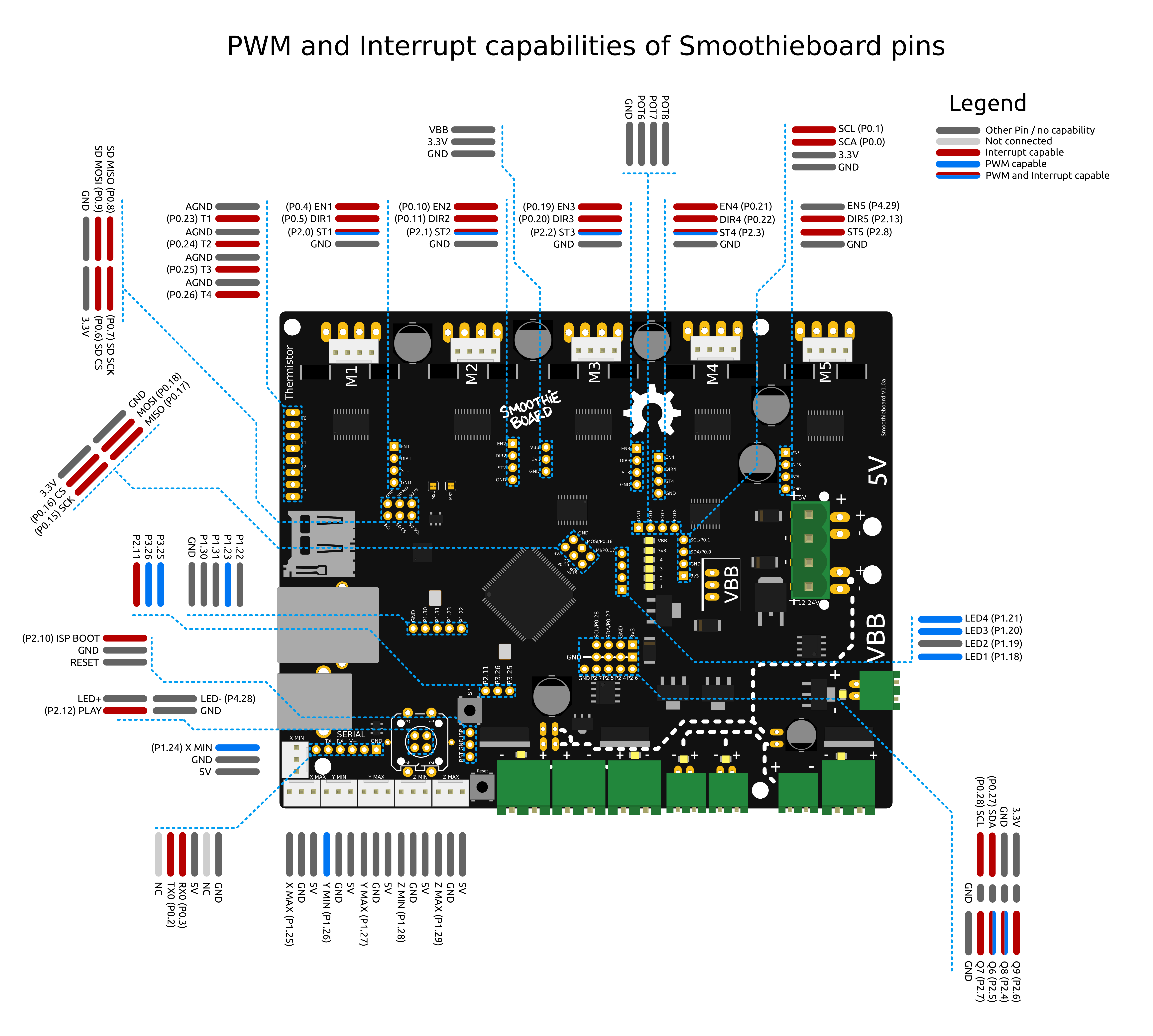
Which pins are which
[!NOTE]

[!NOTE]
Also see the pin usage table

Notes:
- Do not use endstop inputs as outputs (for example to control a solid state relay), this will not work.
Protecting a power input with a fuse
A Fuse is a device which sacrifices itself (gets destroyed and stops letting electricity through) if the current passing through it is higher than a certain value.
As such, adding a fuse between your power supply and a power input on your Smoothieboard protects you against short circuits, overloading, mismatched loads, or any kind of device failure.
You need to choose a fuse with a value higher than your “normal” current for a given circuit. For example, if your heated bed consumes 10A, you want to have a 15A fuse protecting it, that way if everything is fine the fuse does not burn, but in case of a short circuit, it does.
Here is an example of a fuse protecting the mosfet power input:
 Note the fuse must have an adequate rating
Comments:
- Converted the external link to a Fuse to markdown format.
- Reworded the explanation of a fuse for clarity.
- Converted the image to markdown format and updated the path to match the new structure.
- Added a note about the fuse rating in italics for emphasis.
Laser engraving
Smoothie does not ( yet, it’s being worked on ) support native laser raster engraving.
However, as Smoothie interprets G-code unusually fast, a method to do raster engraving is to convert bitmap images into G-code files.
Here are some tools that allow to do this.
The main issue here is sending the gcode fast enough, and there is a tool on the github called fast-stream.py that will send it as fast as possible. I have managed over 100mm/sec feedrate using this script to send the gcode.
Troubleshooting
If you run into trouble, something doesn’t work as it should, head over to the Troubleshooting page for a list of common problems and means of diagnosis.
You can also contact the Community for help if you can’t find an answer in the documentation.
bCNC configuration
bCNC
bCNC is a program that makes it convenient to use Smoothie as a CNC mill or laser cutter, and better yet, it is free! It also comes with several features useful for CNC and laser work, such as a work coordinate system, basic CAM, and a remote pendant web app.
[!DANGER] Be Careful: Failure to properly configure bCNC for use with Smoothie can result in your machine crashing, parts breaking, and being sad. Be careful and check your work.
Getting Started
The first step is to update your SmoothieBoard to the latest, edge, version of the CNC firmware build, as support for bCNC is relatively new. Remember, before you upgrade to a new firmware, backup your config, config-override, and old firmware. See flashing firmware for more help.
The second step is to get bCNC, which is available at bCNC’s GitHub repository. Simply download and extract the archive of bCNC and run bCNC.bat after installing all of the dependencies as listed on the ReadMe. Once installed, select Smoothieboard from the drop-down menu on the communication panel under the File tab and edit the machine configuration under the Tools tab.
Once all of these things are done, you are ready to use bCNC with Smoothie!
Compatibility Note
Unfortunately, bCNC is not 100% compatible with Smoothie. It mostly works, but feedhold does not work as expected, and after you do an abort or stop, bCNC may need to be exited and restarted as it currently does not handle the way Smoothie does abort properly.
Software
Software
All software below either knows how to interface with (or how to generate g-code) for Smoothieware.
3D Printing
- Slic3r - 3D printing slicer
- Cura - 3D printing slicer and host.
- Prusa Control - A beginner-friendly interface for the Slic3r engine.
- Pronterface - 3D printing host. See the guide on the Wiki: Pronterface
- 3Delta Printer Control - 3D printing host especially suited for delta printers.
- OctoPrint - Awesome web interface (Host) for 3D printer control. On the wiki: Octoprint
- Simplify3D - Closed source 3D printing slicer and host. On the wiki: Simplify3D
- Fabrica - Easy to use web control interface (Host)
- Smoopi - Host specifically written for Smoothieware, runs on rpi with touch screen or a desktop.
CNC
- bCNC - On the wiki: bCNC Open-Source CNC host with great preview and other operations. Set machine type to smoothie, and add
grbl_mode trueto your smoothie config or even better use the firmware-cnc.bin build of smoothieware (Note: You must update to the latest version of Smoothieware to ensure compatibility with bCNC). - OpenSCAM.org - Open-Source Simulation & Computer Aided Machining (Free 3-axis CNC Simulator which understands G-Code)
- CNC.js - Open-Source CNC host with lots of features, running in your browser.
- OpenSCAD.org - Open-Source CAD software.
- GCode plug-in for InkScape - CAM, Output GCode from SVG files in Inkscape.
- PyCAM - Open-Source CAM software.
- jscut - Open-Source in-browser CAM software.
- CamBam - Closed-Source, but cheap and feature-full CAM software. Widely used by hobbyists. Video Tutorial
- Fusion360 - Closed-source CAM with very advanced features, free for hobby/fablab/small business.
- Fabrica - Easy to use web control interface (Host)
- Kiri:Moto by Grid.Space - Free web based toolpath generator with support for FDM, Laser Cutting and CNC Milling.
- V-carve is compatible if using this post-processor.
- More links at ShapeOko.com.
- Smoopi - Host specifically written for Smoothieware, runs on rpi with touch screen or a desktop.
- FlatCAM - CAM software for working with PCB design milling
- Tux Plot - A free general use CNC tool for small businesses
- Candle - Open-Source Gcode sender for CNC mills, designed for GRBL but should work fine with Smoothie in grbl mode
- Universal G-code Sender - Set machine type to Smoothieware, and add
grbl_mode trueto your smoothie config or even better use the firmware-cnc.bin build of smoothieware (Note: You must update to the latest version of Smoothieware to ensure compatibility with UGS).
Laser
- GCode plug-in for InkScape - Laser/CNC CAM: Output GCode from SVG files in Inkscape. Video tutorial.
- Visicut - Full laser control application (Host and CAM), has Smoothieware interface. Video tutorial.
- LaserWeb - Web-based full laser control application (Host and CAM), use to generate GCode but not recommended to use as a streamer of rasters as they do not support streaming the smoothie way.
- Fabrica - Easy to use control interface (Host)
- V-carve is compatible if using this post-processor.
- Fast streamer - use for streaming raster images from a host to smoothie. Avoids the pauses when using LW to stream. Can handle upwards of 1,000 pixels/sec.
- Smoopi - Host specifically written for Smoothieware, runs on rpi with touch screen or a desktop.
- Lightburn - LightBurn is layout, editing, and control software for your laser cutter.
- LaserGRBL - For laser engraving and cutting, particularly advanced for engraving
- Polygonia - A tool to easily create repeating patterns for laser cutting: Online tool
Chaining
- This plugin for Fusion360 allows you to start your Gcode files from within Fusion360 directly using Universal Gcode Sender (skipping the step of first saving the file in Fusion360, then opening it in Universal Gcode Sender)
[!NOTE] A few words you will see in this documentation that require a bit of explanation:
- Host software is software that is used to “talk” to your Smoothieboard. It allows you to control the machine (for example “jog” the axes), to “stream” a G-code job, or to upload it to the SD card, things like that.
- Slicing software is software that is used to take a 3D model file, and based on some settings you input, “slice” it into layers, and generate a G-code file that the Smoothieboard can then execute to print a thing.
- CAM software, or CAM Package, for Computer Assisted Manufacturing, is software that is used to take a 3D or 3D file, and based on some settings you input, transform it into a list of tool movements (G-code file) for a machine that uses a tool to remove material from a workpiece.