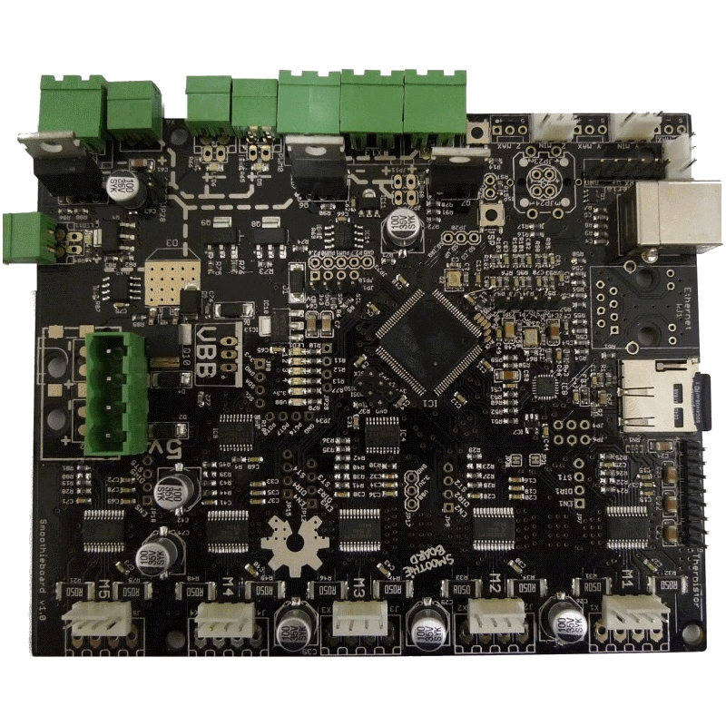
SmoothieBoard is an Open Source Hardware CNC controller board based on the LPC 1769 or LPC1768 Cortex-M3 chip.
It is intended to run the Smoothie modular firmware ( GPL too ), and is targeted at 3D Printers, Laser cutters, CNC Mills, Pick and place and other small-sized CNC machines. Larger machines can be driven using external drivers.
Status
The Kickstarter for the 5 axis version of Smoothieboard has been completed and all of the rewards have been shipped. Thank you to all the backers who made this possible! You can now buy Smoothieboards here.
What can it be used for ?
The Smoothie firmware is designed for maximum usefulness in mind. The same thing goes for SmoothieBoard. Here are some of the machines it's already possible to control using the current firmware and a SmoothieBoard:
- 3D printers, like repraps including extruder control, bed and hotend temp control.
- CNC mills, CNC lathes.
- Laser cutters
And with more to come : laser engraving, SMT pick and place machine, foam cutter, delta robot, and anything else you care to imagine.
Getting one
You can now get a smoothieboard here.
Features
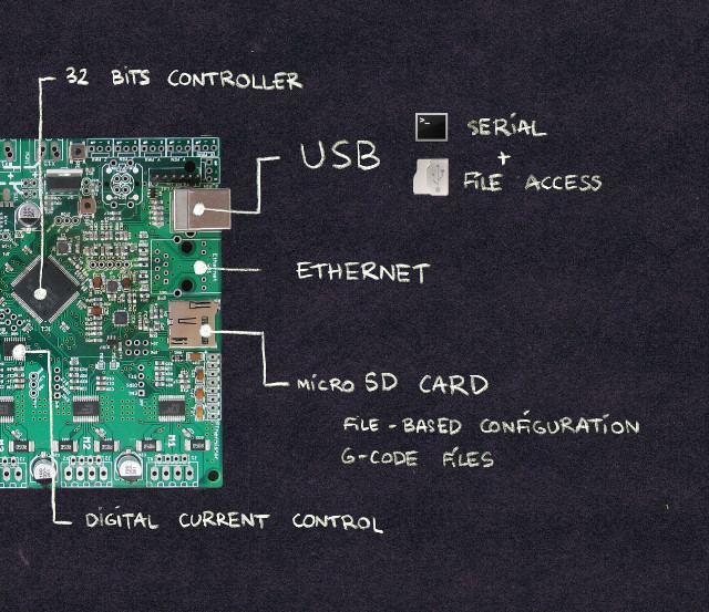
Microcontroller
- NXP LPC 1768/9 32-bits Cortex-M3 MCU, running at 96 to 120Mhz. 512kB Flash, 64kB RAM.
- Drag and drop flashing : simply drop a new firmware file to the smoothieboard to update.
- USB2 Composite device : shows to the computer as both a Serial device, and a Mass Storage device ( exposing the SD-card ), à-la mbed.
- Ethernet
- microSD card file storage.
Stepper drivers
- 3 to 5 Allegro A4982 stepper drivers.
- Each capable of driving bipolar steppers up to 35V and 2A.
- 1/16 microstepping.
- TSSOP package allows for much better thermal handling than commonly used A4983/8.
- Digital control of the current setting for each driver instead of trimpot manual control.
Power outputs
- Up to 3 SMT ZXMN4A06 ( 5A, up to 24V ) Mosfets sharing a power circuit
- Up to three thru-hole ( AOT240L : 12A, up to 24V ) Mosfets sharing a power circuit
Power inputs
- Main 12-24V ( Stepper drivers ) power can be connected using a 3.5mm or 5mm screw terminal, SMT power jack connector, or a Molex connector ( ATX-harddrive style )
- 5V input can come from a 3.5mm screw terminal, a SMT power jack connector, or a Molex connector as above or taken directly from the USB cable. 5V can also be supplied by a 5V regulator installed on the board.
- Each of the two Mosfet couple can take its power from either its own 3.5mm screw terminal, or SMT power jack connector, or be connected to the main stepper driver circuit using jumpers.
Inputs
- 4 Thermistor ( ADC ) inputs.
- 6 Endstop inputs. (All VCC pins are a common voltage. There is a solder bridge SJ2 below the board to connect them to either +3.3V or +5V )
- Play/Pause LED Tactile Button (Not populated by default)
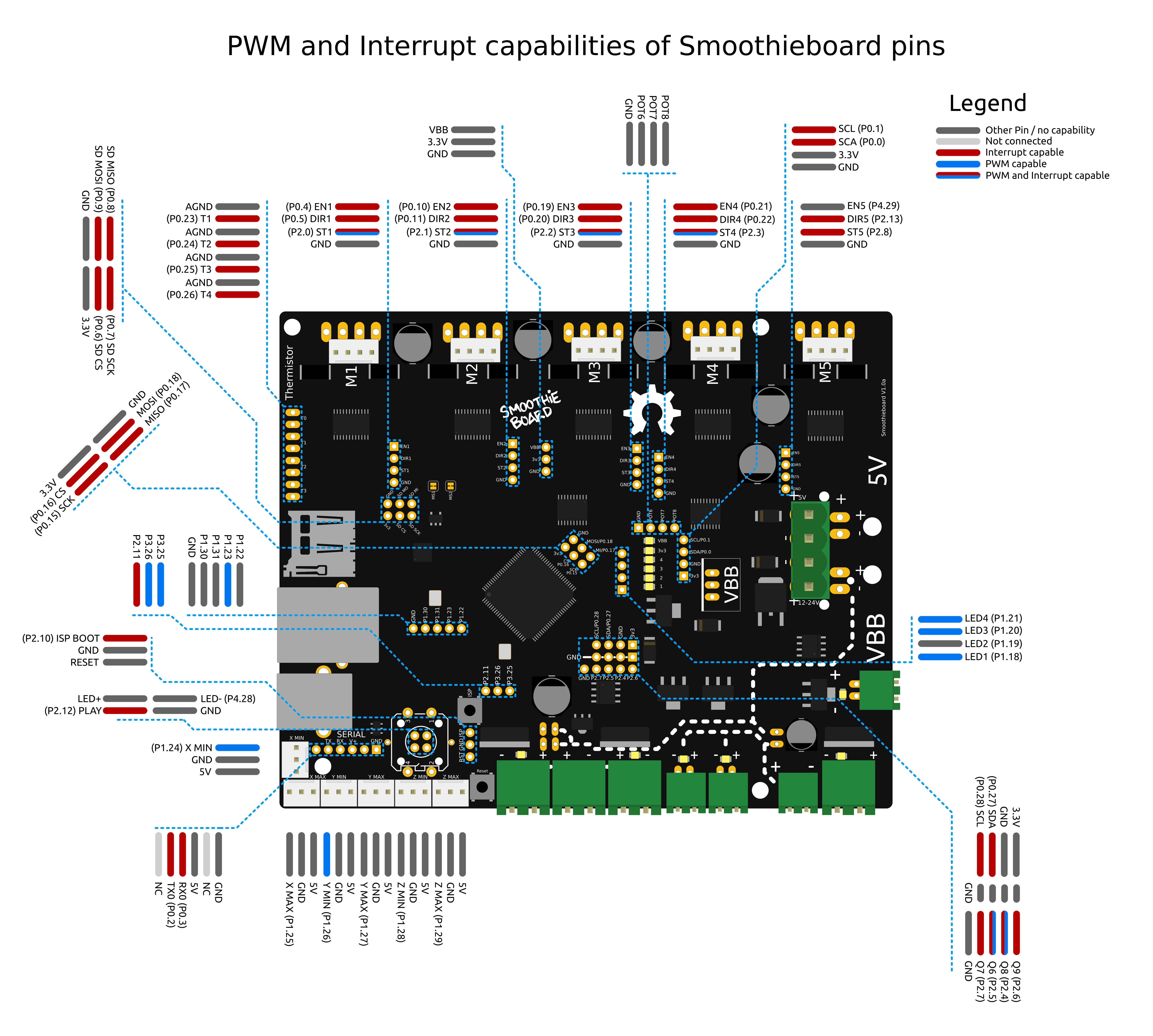
Extensibility
- SPI connector, I2C connector, Serial connector
- Lots of pins broken out ( Including step, direction and enable pins for the stepper drivers, and mosfet pins )
- 13 Additional GPIO pins broken out
- 4 LEDs, many connectivity options
Firmware
- Runs the highly-modular Smoothie firmware, see home page for more info.
Sources
- Oh and by the way, it's all Open Hardware ( GPL-licensed ). You can find the Eagle files on GitHub.
- If you are just hunting for part numbers, the bill of materials is also available in *.xls format on GitHub
- Components BOM
- Connectors BOM
Design
- Dimensions are 130x105mm
- 3D files can be found here on Thingiverse to design cases and plates and such.
- Schematics
Documentation
Stepper motors
Stepper motors are indicated as X, Y, Z ( cartesian movement axes ) and E ( 3D printer extruder ). However, in Smoothie, stepper drivers are alpha, beta, gamma and delta. They are equivalent, in the same order.
This is because if you use for example a non-cartesian arm solution ( for example a rostock, delta or scara robot ), then individual stepper motors don't match specific cartesian axes, things are a bit more complicated. Thus the greek letter naming of the drivers.
For each stepper motor you get two options :
- 3.5mm : mostly used for the larger screw terminals ( Blue screw terminal, or green base and green screw terminal )
- 2.54mm : mostly for smaller pins, or more sophisticated pin-like connectors. ( Keyed white or naked pins or green mini screw terminals )
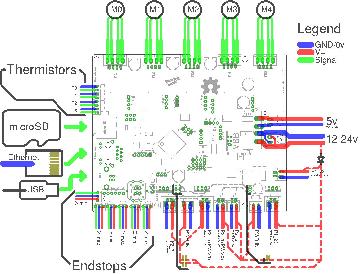
Stepper motor power input
This has two inputs side by side : one for 5V ( this is optional, you will probably be providing 5V via USB ), and one for VBB ( the stepper motors ( and optionally mosfets ) power input ), that is 12 or 24V.
There are several options there. You can solder an ATX molex connector : the same kind you would find on ATX power supplies, that goes into 3-1/2" IDE hard drives.
This allows you to simply plug an ATX power supply in there. However, do not use this for high current applications ( >10A ) as that can be too much for those connectors.
You can also solder 3.5mm connectors ( not recommended unless you use little power ), or 5mm connectors ( Big grey screw terminal, or green base and green screw terminals ).
Finally, for the VBB input, there are pads to solder a SMT Jack power plug ( the kind you commonly find on 12V wall plugs ), which is nice to have if you are going to plug/unplug your board a lot.
Small mosfets
These are two small SMT mosfets : ZXMN4A06 ( 40V/5A )
They are usefull for small loads like hotends, fans, led lighting, relays, etc …
The power input is shared by the two mosfets. Meaning the power input ( 3.5mm pins at the top ) provides power to both of them.
And then each mosfet has its own two-pin output, with the choice between 2.54mm ( not recommended except for light load things like fans ) or 3.5mm ( Blue screw terminals, or green base and green screw terminals )
You can also take the power from VBB instead of from the power input, using jumpers, see the dedicated part in the non-border stuff section below.
Big mosfets
These are two big mosfets : AOT240L capable of switching 12.5A at 24V.
They are usefull for big loads like hotends, heated beds, and crazy things.
The power input is shared by the two mosfets. Meaning the power input ( 5mm and SMT Jack power connector in the middle ) provides power to both of them.
And then each mosfet has its own two-pin output, with the choice between 2.54mm ( not recommended except for light load things like fans ), 3.5mm or 5mm.
We recommend using 5mm connectors ( Blue screw terminals, or green base and green screw terminals ) for all connectors.
You can also take the power from VBB instead of from the power input, using jumpers, see the dedicated part in the non-border stuff section below.
Endstops
There are 6 endstop connectors, one min and one max per axis. Though you probably just want min for homing, max can be used to limit movement, as can min.
The inputs are 3.3V logic, but 5V tolerant and hardwired with on-board 1k pull-up resistors connected to 3.3V or 5V based on the setting of solder jumper SJ2. The input circuit also contains a series resistor so you generally need to use a sensor or switch which actively switches to GND.
Each endstop connector is a 3-pin 2.54mm, providing Vcc, GND, and the actual input endstop pin. (Vcc is either 3.3V or 5V depending on the state of solder jumper SJ2).
You can connect either 2.54mm pins, or 2.54mm screw terminals here ( Keyed white or naked pins or green mini screw terminals )
USB
USB provides the main means of communication with the host computer. The connector is mini-USB.
Ethernet
The RJ45 connector is optional. When plugged in, the smoothieboard will serve a web interface that will allow for control of the machine. link
MicroSD
The microSD card stores the config file, gcode files, the web interface files, and other, futury stuff.
Thermistor inputs
Thermistors are mostly used for hotends, and heated beds. In conjunction with mosfets and heating elements, they allow for precise temperature control.
Each thermistor has a couple of 2.54mm pins ( allowing for pin connectors or screw terminals ). 4 thermistors means a row of 8 pins. ( Keyed white or naked pins or green mini screw terminals )
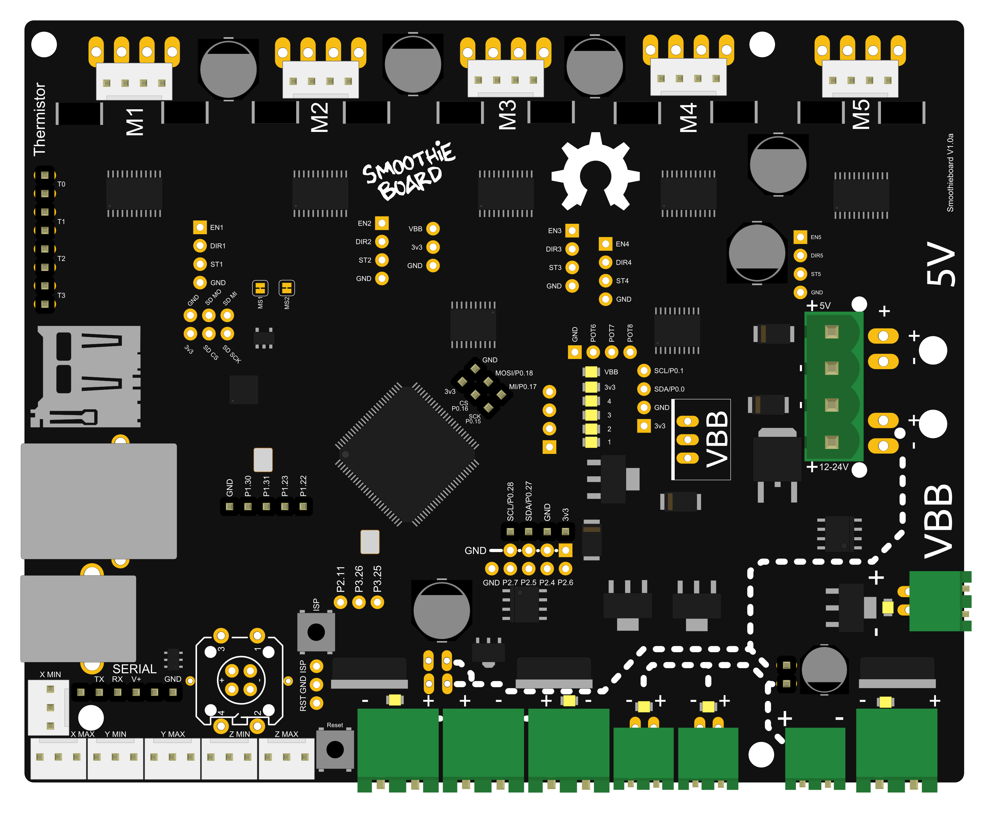
All essential connectors being broken out to the perimeter of the board, the rest is on the board itself, where it's a tad less easy to reach ( but we can't have 5 meters of perimeter, that'd be dumb. )
All of them are optional and not soldered by default.
Here is a list of those connectors, in clockwise order :
Play/Kill button
The Play/Kill button is a button with a LED in it. The LED lights up when the board is printing or moving. When you click the button the board goes into a HALT state and kills whatever was printing and turns everything off and the LED flashes rapidly.
The component is this LED Tactile Button. Solder it if you want to have some killing fun. Most prefer red, as it's killy, but there are other choices.
Extra pins breakout
Mystery !
Other extra pins breakout
Breaks out un-used pins 1.30, 1.31, 1.23 and 1.22. For extension fun.
SD card SPI breakout
The SD card interfaces with the MCU using SPI communication. In case you would want to not plug the SD card into the smoothieboard, but connect an external SD card connector instead, those SPI pins are broken out.
See pictures for pinout.
Stepper motor breakouts
All stepper motors have their enable, step and direction pins broken out. So if you burn one ( which is very difficult, simply don't connect/disconnect them with the power turned on ), you can connect a replacement driver.
Extra stepper driver connector
You can connect an additional stepper motor driver ( like a pololu-like board ) to the board. This is useful for example to add a second extruder.
The step, direction, and enable pins are broken out, as well as VBB, GND and 3.3V.
SPI breakout
The SPI breakout allows you to connect stuff that talks SPI. For example a second SD card. Or something else, your turn to think of something.
LEDs breakout
There are 4 leds on the smoothieboard, in a row, mostly used for debugging right now.
Their pins are broken out so they are not completely wasted and you can use them if you really need them.
I2C breakout
I2C is broken out to connect to peripherals. Lots of stuff talks I2C. However the I2C tends to be very noisy so the connections need to be kept very short.
Small mosfets power select
This is a pair of pins for jumpers. When nothing is soldered, the power for the small mosfets is taken from the small mosfets power connector.
When the pins are soldered, and the jumper connects them to each other, power for the small mosfets is taken from VBB ( the stepper motors power circuit ).
Don't connect the power input and the jumper at the same time, that'd be bad, probably.
Mosfets breakout
All pins for control of the 4 mosfets are broken out here. In case you want to do something with them.
Big mosfet 1 and 2
Those may or may not come pre-soldered. If they are not pre-soldered, you can solder mosfets you like here.
Big mosfets power select
See the same for small mosfets. It's just two jumpers instead of one, but it's the same thing.
Reset and bootloader buttons
Breaking pins out doesn't cost much, right…
