Your guide to installing Smoothieboard in a CNC Milling Machine
Although not as common as the Smoothiefied 3D printer, the CNC mill machine is fairly simple to Smoothiefy.
This is a step-by-step guide to connecting your board to the various components of the CNC mill machine, configuring everything, from the beginning to actually milling material.
This guide is a community effort, and this page is a Wiki. Please don't hesitate to edit it to fix mistakes and add information, any help is very welcome.
|
Table of Contents
|
Unboxing
Your Smoothieboard comes with a microSD card in the microSD slot.
The boards come pre-flashed. With a basic configuration file installed on the SD card, no preparation is needed before you can connect Smoothieboard to your computer and start interacting with it.
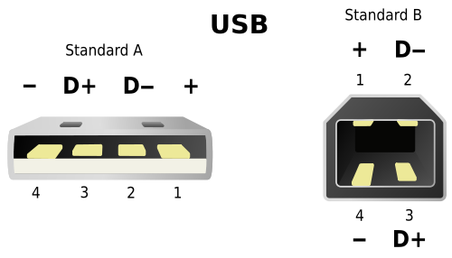
A good first step is to connect your board to your computer to familiarize yourself with it. Connect a USB-B cable to the USB connector on the board, and to your computer.
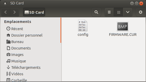
A moment after connection, your computer will recognize the Smoothieboard as a USB Mass Storage Device (like a USB disk-drive or a SD card reader), showing you the files present on the SD card. Drivers are needed for Windows 7/8, while Linux and Mac OS X directly support the device, you can find those drivers here.
This allows you to add, copy, edit or delete any file you'd like. Already present on the SD card is a file named "config". This file contains all of the configuration options for your board and is read when you start or reset your board. You edit the configuration simply by editing this file in a Text Editor, saving it and resetting the board. No need to recompile or flash the board.
The SD card can also be used to flash a more recent version of the firmware to your board, see where to get the binary file and how to flash it via the SD card.
It can also be used to store and play G-Code files, see Player.
USB Mass Storage is not the only thing you get when you connect the board. The board also exposes a USB CDC Serial interface, allowing you to send G-Code and receive answers. (There is also a DFU interface for flashing firmwares but that's mostly for developers).
The CDC (Serial) interface is the interface host programs like Pronterface use to allow you to interact with your machine. If you are already familiar with it, you can try connecting right now and get an answer from the board. If not, we explain it all later in this guide.
Warnings
Before you start wiring your machine's elements to the board, there are several things you need to keep in mind and be careful about during all of the assembly.
Make sure you read this. Seriously.
Polarity
Always make sure the polarity is correct when wiring in power inputs (coming from the Power Supply). Reversed polarity can damage or destroy all or part of your board. Polarity is indicated on the board itself by the + and - signs. Double check. On older versions of the board, markings are partially hidden by the connector, making it confusing. Rely on only the diagrams.
To check the polarity of your power source, attach your multimeter probes to the two wires of your power source respectively. If the voltmeter reading is positive it implies that the red probe is connected to the positive wire (+) and the black probe to the negative wire (-).
The main (labeled VBB) power input has a reverse polarity protection, however, it will not hold forever. As soon as you notice something is wrong, turn the power supply off and check again.
Disconnecting
Never disconnect or connect stepper motors from the stepper motor drivers while the board is powered (i.e., when the Power Supply is turned on).
The drivers have very good protection against most possible problems and are very hard to destroy accidentally. But it is possible.
Shorts
Be careful that nothing metallic ever touches the board while it is powered on. Falling screwdrivers, nuts and bolts can cause shorts and destroy the board.
Check the board before powering it on.
Do not press the reset button with anything metallic, as you could slip and cause a short, use a plastic screwdriver or the like.
Use the right connector
Always check the schematic before connecting power sources (coming from the Power Supply) to the board. Connected to the wrong connector can destroy components. A common example of this problem is plugging a power input cable, into the connector for an output, or plugging the limit switches in backwards.
Crimping
Make absolutely sure of your connections using crimps or screw terminals, from wires to any type of connector, are very careful and well done. Connections (to the stepper motors for example) lost while the machine is running can destroy your board.
Markings
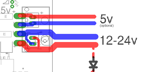
In the case of the VBB power input, be careful. If your board came with connectors pre-soldered, the 5mm connector is present, and the polarity of that connector is that of the large traces in the wiring diagram to the right (red is +, blue is -). On some boards, the marking on the boards may be hidden by the connector itself, so for VBB, do not rely on the markings on the board, but on the diagrams on this page. However, if you did not get your connectors soldered, and want to solder a 3.5mm connector instead of a 5mm connector, also note that the polarity is the opposite.
USB v Ethernet
USB can, in some setups, be subject to interference, which causes disconnections, and can ruin your work. This is very hard to prevent if it happens even in normal conditions. Ethernet, on the other hand, does not have this problem: save yourself the trouble, and use Ethernet right away. It's very nice. See Network for information on how to set it up.
Destroying your board
If you receive a bad board, you will get a replacement. But if you destroy your own board, your only options will be to fix it yourself (which can be quite difficult), or get a new one.
This is why it is very important you make sure you do not destroy your own board. Smoothieboard is reasonably protected, but there are still things that will destroy it. The general idea is: if a part of the board gets too much power, it will get destroyed. Here are some common mistake users do that cause the board to get too much power and die:
- Plugging 12-24v (motor power) into anything you are not supposed to. Like the 5V line, or an end-stop or thermistor input for example. Problems with the 5V or 3.3V power are not as much of a problem as the board is 5V-tolerant, so wrong connections and shorts should be okay as long as they do not last too long.
- Shorting 12-24v to anything else, which is essentially the same as plugging it into a place you are not supposed to (see above). This can happen by dropping a metal object onto the board, bad soldering, loose wires, un-protected wires, etc …
- Using an inductive load (like a motor, fan or solenoid) on a MOSFET, without a diode across (see Fan documentation).
The general idea here is: always make sure everything is clean, and double-check everything before turning the power on. You can not learn by making mistakes here, as mistakes will likely cost you your board.
Electrostatic discharge can also destroy your board : make sure you properly ground everything.
For a good read about safety, you can refer to the RepRap Wiki documentation on the subject
Main Power Input
Without power, your board can not do much. The board uses power to move stepper motors, and power heating elements, fans, and others.
How to choose a power supply unit (PSU) :- Voltage (V)
- Can be from 12 to 24V. While most of the components on the Smoothieboard are rated up to 32V, it is not recommended or supported to use that voltage. 12V PSUs are more common, and generally cheaper. However, the higher the voltage, the more you will get out of your stepper motors. This is the reason some designers use 24V PSUs. However, be careful that with a 24V PSU, you will need 24V fans, and will need to reduce the PWM setting for your heating elements.
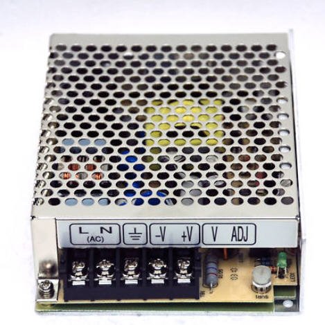
Setup
Make sure you use a Regulated Power Supply, make sure you connect the ground wire for the mains to the power supply, and if it has a fan, make sure it has sufficient space around it to let air flow and cool it appropriately.
To wire the power supply unit to mains (wall AC power), make sure you connect the right colored wires to the right connectors on the PSU. The 3 connectors are "live", "neutral" and "ground". Color changes from cable to cable, you can find charts for your specific country/cable on the internet, but the following colors are the most common:
- US: Black = Load/Live, White = Neutral, Green = Earth
- Europe: Brown = Load/Live, light Blue = Neutral, Yellow/Green = Earth
Once the wires connected to the PSU, make sure none of your computers is doing something important (like a system upgrade). In case something goes wrong, plug the PSU into a power strip with an on/off button. Then turn that button ON. If your house loses power, you did something wrong. If an LED illuminates on the PSU, everything is fine: unplug the PSU and continue.
Don't die
NEVER manipulate mains (220/110V) power wires while they are plugged into the wall plug. Unpleasantness and/or death are common consequences of not respecting this rule.
Ground your printer's frame by connecting it to the Earth terminal on your power supply. In the (unlikely) event that a power supply wire comes undone and touches the printer's frame, this will prevent you from getting an unpleasant and/or deadly shock.
5V
Your board needs two sorts of power to work : 12-24V power to turn motors, heat hotends, etc, and 5V power to power the microcontroller ( the brain ).
There are three ways to provide 5V power to the board :
- By plugging a USB cable in, USB cables provide 5V
- By soldering a voltageregulator to the board ( and providing 12+24V, which the voltage regulator then turns into 5V )
- By providing 5V directly to the 5V power input ( next to the VBB power input )
Now that the PSU is getting mains power, your PSU is converting it into 12 or 24V power. You need to connect wires from it to the Smoothieboard to provide power.
The most important thing is to respect polarity : + goes to +, - goes to -. On the PSU, + terminals are indicated as +, V+, 12V+ or 24V+. Ground (-) terminals are indicated as -, V-, COM or GND.
On the Smoothieboard they are indicated simply as + and -.
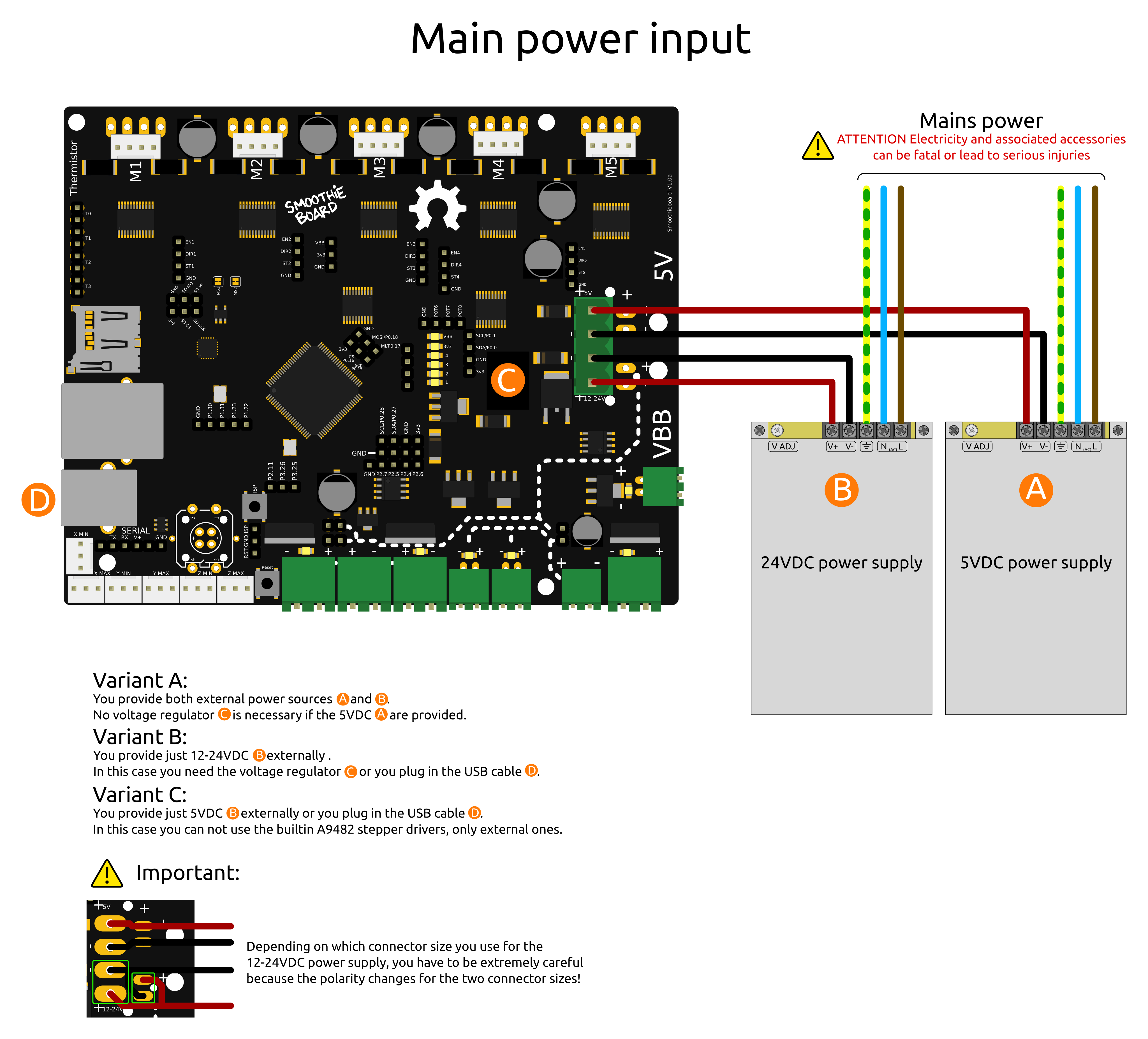
By convention, black (sometimes brown) wires are used for ground, and red (sometimes orange, white or yellow) wires are used for power connections.
Once the wires are correctly connected, you can turn the PSU ON. If everything was done correctly, the red LED (marked VBB) on the Smoothieboard will light up brightly.
Be careful
If it does not, immediately turn the PSU off.
Check polarity, and check all the connections are strong and properly done.
When you turn the PSU on, make sure you are ready to immediately turn it back off.
Now that the board has power, you can use that power to move things!
Emergency stop
It is recommended you setup an emergency stop button on your machine, so that in case of a problem, you can easily and quickly turn the machine off. For information on how to do this, please read EmergencyStop.
Stepper Motors
A bit of theory :
« A stepper motor (or step motor) is a brushless DC electric motor that divides a full rotation of the motor into a number of equal steps. The motor's position can then be commanded to move and hold at one of these steps without any feedback sensor (an open-loop controller). » (Wikipedia)
Because they work by steps, and you can accurately control how many steps you move in each direction, stepper motors are a very practical way of moving things to a desired position. This makes them great for most CNC applications.
Smoothie comes with stepper motor drivers designed for bipolar stepper motors, with a maximum current rating of 2 Amps.
Wiring
Direct wiring
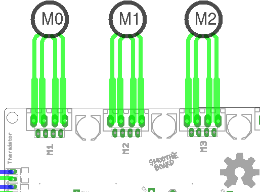
Bipolar stepper motors have two poles (bi-polar). Each pole is connected to two wires. That's 4 wires coming out of your stepper motor. These have to be connected to your Smoothieboard.
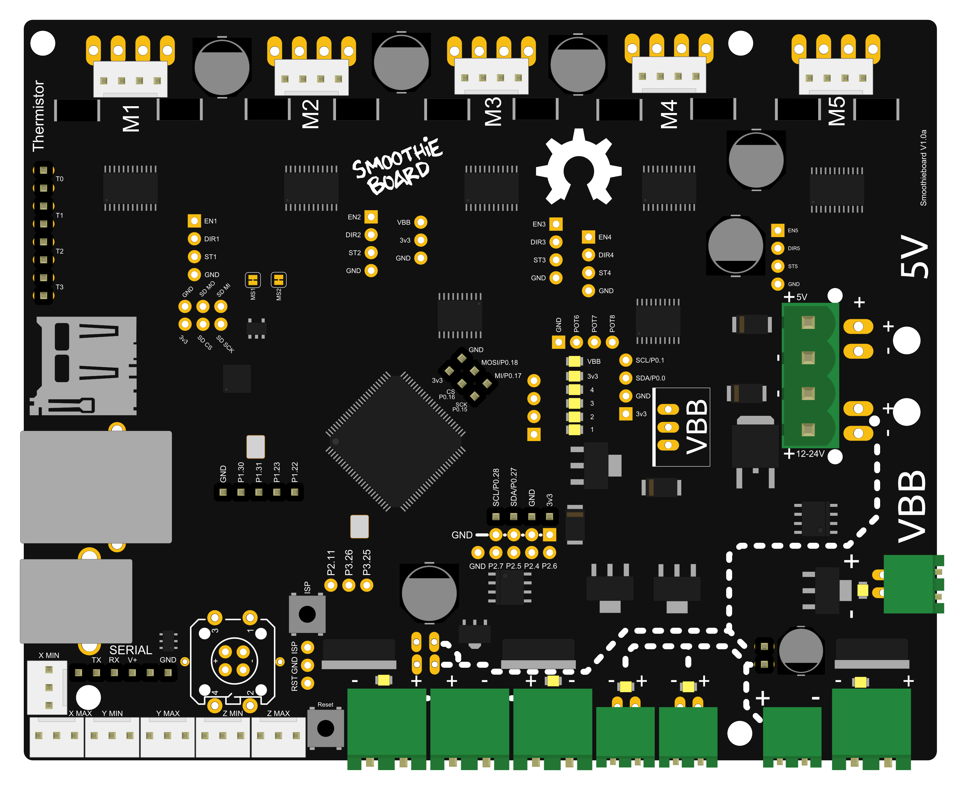
Each stepper motor driver on the Smoothieboard has 4 connections to that effect. (Stepper motor drivers are labeled M1, M2 etc …)
The tricky thing is often to find out which wires connect to which poles. If you just wire things at random, you have a chance it will work, but let's be scientific about it. Several methods:
Now to connect the wires to the Smoothieboard. Let's call one coil A, and the other coil B. It doesn't matter which is which. Polarity also doesn't matter, all it changes is the direction the motor turns, and you can change that in the configuration file. Now simply connect your two wires to the Smoothieboard's 4 pins for that stepper motor driver as such : AABB or BBAA. Other combinations like ABBA or ABAB will not work.
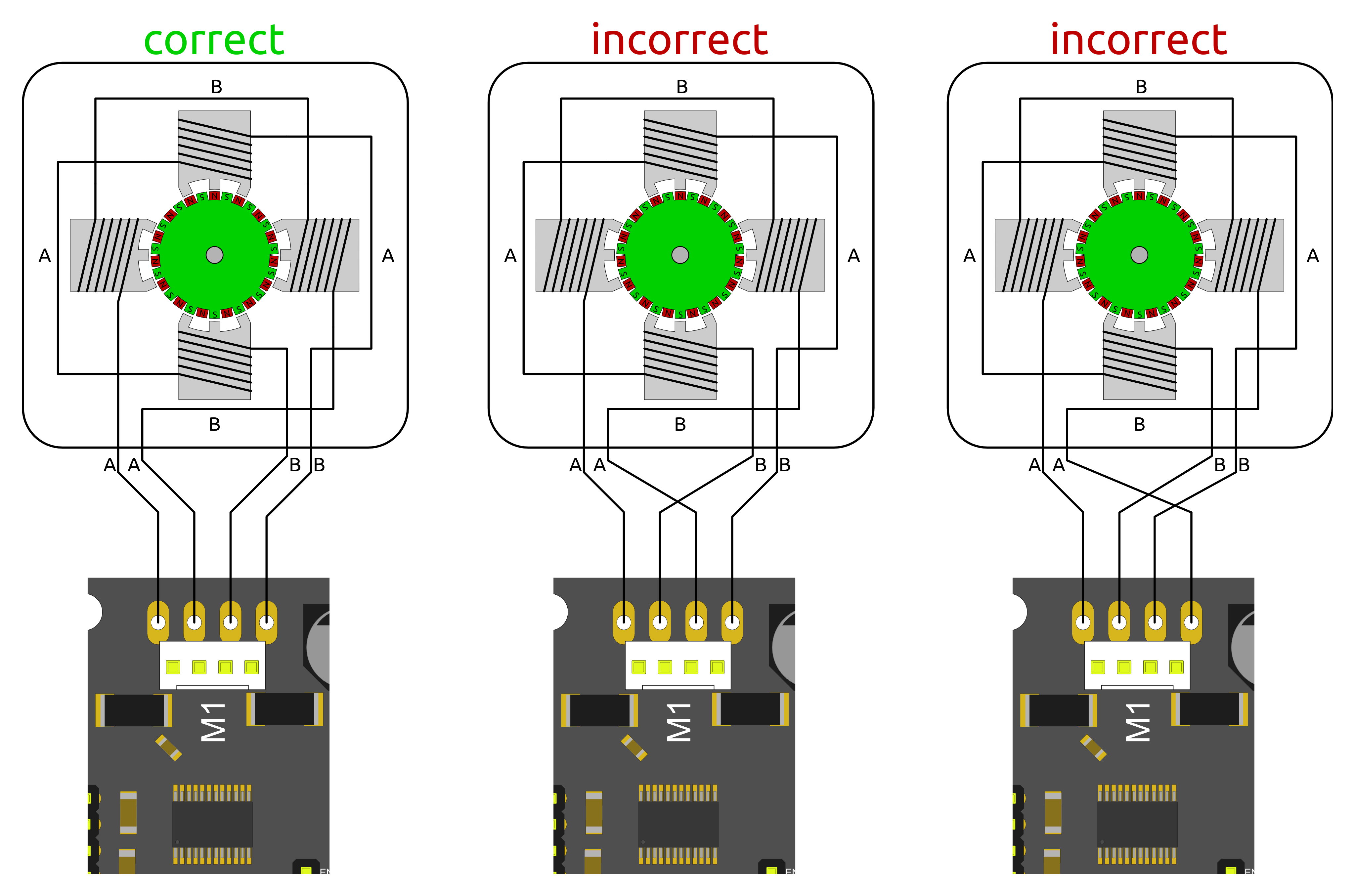
Once your stepper motor is properly connected to your Smoothieboard, it is ready to be controlled.

Wiring a stepper motor to a stepper motor driver.
In this example, a stepper motor is connected to the M1 driver, and power is provided to VBB ( the main power input ).
External Stepper driver
If you want to use larger stepper motors than the Smoothieboard's drivers can handle ( 2A max ), you need to use external stepper drivers.
You can find detailed information on how to wire an external stepper motor driver to a Smoothieboard in the External driver appendix.
Configuring
Example configurations are available in github https://github.com/Smoothieware/Smoothieware/tree/edge/ConfigSamples.
You can also refer to the Configuration documentation.
Current
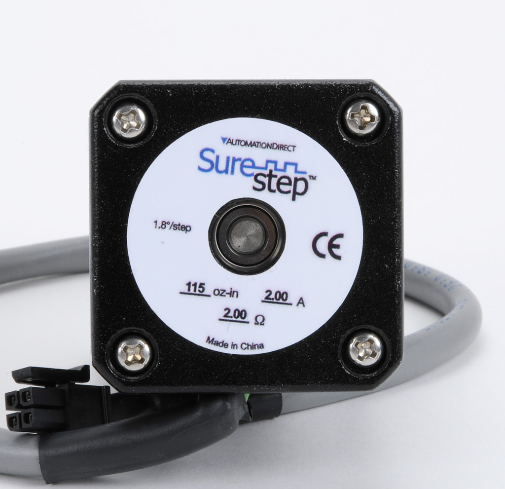
The first thing you have to do is tell the stepper motor drivers what is the current rating for your stepper motors is. To drive the stepper motor correctly, the driver has to know the motor's current rating.
Each stepper motor model has a precise current rating. You can drive your stepper motor at a lower current, which will make it more silent, but also less powerful. But you can not drive the motor at a higher current than it is rated at. This would cause overheating, and possibly skipped steps.
The rating is often written on your stepper motor's label ( see picture on the right ). If it is not, you can get it by googling the stepper motor model number, or by contacting your seller or manufacturer.
Once you have the correct rating, you can set the corresponding parametr in the configuration file.
Smoothie has a funny way of naming stepper motor drivers. Instead of naming them X, Y or Z, because this makes no sense in non-cartesian robots like delta robots, we name the drivers using Greek letters so they are arm application agnostic :
| Label on the Smoothieboard | M1 | M2 | M3 | M4 | M5 |
|---|---|---|---|---|---|
| Axis in a Cartesian machine | X (left-right) | Y (front-back) | Z (up-down) | E0 : First extruder | E1 : Second extruder |
| Greek letter | α (alpha) | β (beta) | γ (gamma) | δ (delta) | ε (epsilon) |
| Current setting configuration option | alpha_current | beta_current | gamma_current | delta_current | epsilon_current |
Now, as described in the "Unboxing" paragraph, connect the board to your computer, open the "config" file with a text editor, and change the configuration value for each stepper motor driver to the correct value.
For example, if your alpha stepper motor has a current rating of 1.68A, edit the corresponding line to read :
alpha_current 1.68 # X stepper motor current
Do this for each stepper motor you have to connect to the board. (If you have a Cartesian robot, see which motor connects to which stepper driver in the array above. If you use another type of arm solution, see the specific documentation.)
Steps per millimeter
A stepper motor driver operates in steps. It moves a certain number of steps in one direction, then a certain number of steps in another. You think in millimetres. You want your machine to go to a certain position in millimetres, then another position in millimetres.
You need Smoothieboard to convert the millimetres you ask of it, into steps the stepper motor driver understands.
That conversion depends on your exact arm solution. The most common, and the simplest, is the Cartesian arm solution, and it is the one we will focus on here. Documentation for other arm solutions can be found separately.
In the case of a Cartesian arm solution, you simply convert a certain number of millimeters to a certain numbers of steps. That is the steps_per_millimeter configuration option that you have to set for each stepper motor.
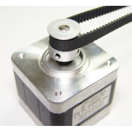
To compute it, you must multiply a certain number of factors.
- The object you move moves a certain number of millimetres for each rotation of the stepper motor. (This depends on the characteristics of the belt/pulley, or lead-screw system you are using.)
- The stepper motor moves a certain number of full steps per rotation. That is usually 200. (But it can be 400.)
- Each step is divided by the stepper motor driver in a certain number of microsteps. It is that number, and not the number of full steps, that we want. Smoothie always divides steps into 16 microsteps.
The formula is as follows :
$\text{(micro) steps per millimeter} = ( \text{full steps per rotation} * \text{microsteps per step} ) / \text{millimeters per rotation}$
To help you, there is an awesome calculator by the awesome Josef Prusa: http://calculator.josefprusa.cz/
Once you know the correct value for a given stepper motor driver, set it in the config file.:
alpha_steps_per_mm 80 # Steps per mm for alpha stepper
Do this for each stepper motor driver.
In the case of your extruder stepper motor, the principle is the same, but the value is extruder_steps_per_mm.
Direction
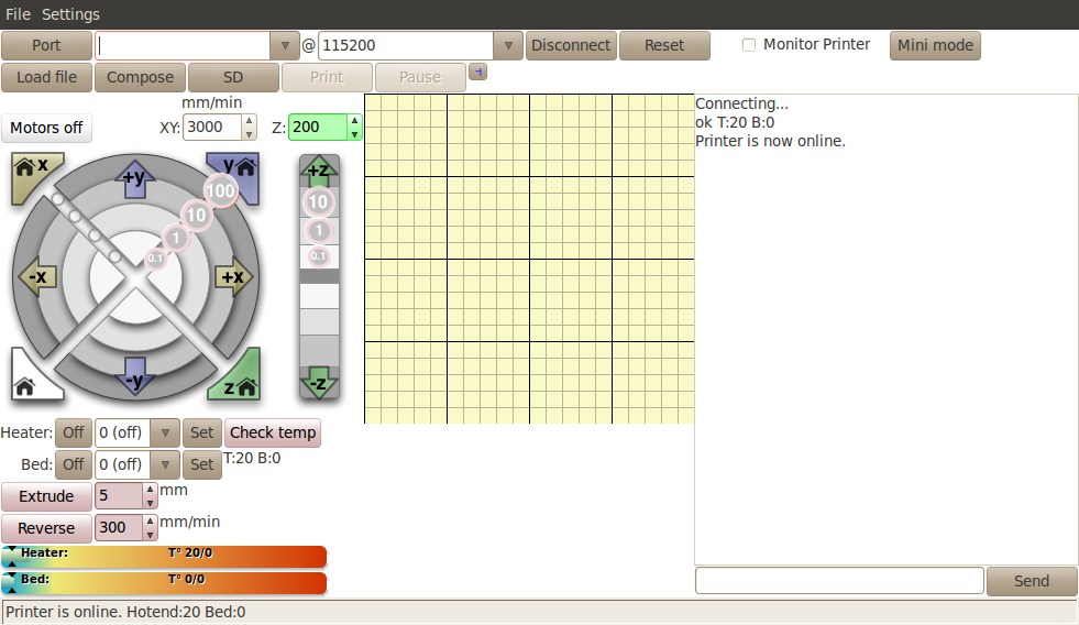
It is now time to test your stepper motors. For this you will need to use host software like Pronterface or the web interface.
Now connect to your Smoothieboard over the serial interface. Power your machine on by plugging the PSU into the wall.
Now you need to move an axis to make sure the stepper motor is turning in the right direction. In Pronterface, click near the yellow arrow marked "+X".
Your X axis will move. If it moved to the right, great! Everything is fine, and you have nothing to change. If it moved to the left, you need to invert the direction of that axis.
You do this by editing the configuration file, and inverting the direction pin for that stepper motor driver :
alpha_dir_pin 0.5 # Pin for alpha stepper direction
Becomes :
alpha_dir_pin 0.5! # Pin for alpha stepper direction
This is for your axes. In the case of your extruder, the config value is extruder_dir_pin.
Save the config file, reset the Smoothieboard, connect again using Pronterface. Now the axis will move in the right direction.
Do this for each axis.
Moving bed
If you have a moving bed in the Y axis for example, as opposed to a moving tool, be careful : what matters is the direction of the head relative to the bed, not the direction of the bed relative to the machine. It's very common to get confused and invert your Y axis on moving bed machines (or not invert it when it should be). Basically, if an asymmetrical object looks like the model when it is printed, then your Y axis is correct, otherwise you need to change your configuration.
Endstops
End-stops are small interrupters that you put at the end of each of your axes. When you boot your machine up, Smoothie has no way of knowing the position of each axis. When it starts a print, Smoothie moves the axis until it touches that interrupter, and when it is hit, it declares that that is position 0 for that axis. And does so for all axes.
This allows Smoothie to then precisely know where everything is relative to that initial position. It is quite convenient as it saves you the hassle of actually moving the machine into that position when you want to start a print. Automation is great.
However, end-stops are not necessary, you could do without them. They are just so convenient that most machines use them.
End-stops can also be used as Limit Switches which prevent the machine from attempting to move beyond the physical limits of the axis (by pausing/stopping movement when triggered), see the Endstops page for details about configuring Smoothie to use End Stops as limit switches.
Endstop Wiring
This will concentrate on the most common type of end-stops : the mechanical ones. Other types exist like optical or hall-o sensors, see the dedicated appendixes for those.
TODO : Do those appendixes
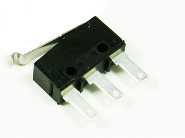
Mechanical end-stops are simple interrupters : when not pressed, they do not let the current pass, when pressed, they let the current pass. By connecting a digital input pin on the Smoothieboard to the interrupter, and connecting the other side of the interrupter to Ground, the Smoothieboard can read whether or not it is connected to Ground, and therefore whether or not the end-stop is pressed.
Most mechanical end-stops have 3 connection points, to which you have to attach your wires :
- C : Common
- NO : Normally Open, meaning it is not connected to C when the interrupter is not pressed, and connected to C when the interrupter is pressed.
- NC : Normally Closed, meaning it is connected to C when the interrupter is not pressed, and connected not to C when the interrupter is pressed.

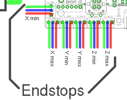
Wiring a basic NC endstop
You want to connect the Signal ( green in the schematic ) and Ground ( blue in the schematic ) pins for the end-stop on the Smoothieboard, to the C and NC connection points on the end-stop.
For each endstop, we connect C to Signal and NC to Ground because this means the digital input pin ( endstop connector ) will be connected to Ground in it's normal state and cut from Ground when the button is pressed. This approach is less prone to noise than the reverse. See here for more information.
Another positive effect of this approach is, that if a wire breaks for some reason you get the same signal as if the endstop is pressed. That makes sure that even with a damaged wire you are not able to overrun the endstop.
Order is not important as polarity is not important here.
Make absolutely sure that you do not connect VCC ( red ) and GND ( blue ) to a mechanical (microswitch) endstop! Depending on your wiring that may fries your smoothieboard instantly or when the switch gets pressed. There is a wiring where this not happens and you switch the signal between VCC and GND, but if you're not careful enough you damage your board.
You want to connect your X end-stop to the X min pins, Y end-stop to the Y min pins, and Z end-stop to the Z min pins.
Testing
The default configuration most probably already has everything you need : the pins are already correct and the default speeds are reasonable.
Once they are wired, you can test your end-stops.
To do this, reset your Smoothieboard, then connect to it using host software like Pronterface or the web interface.
Now connect to your Smoothieboard over the serial interface. Power your machine on by plugging the PSU into the wall.
Now in Pronterface, home one axis by clicking the small "home" icon for that axis. Begin with X, then Y, then Z.
If your axis moves until it hits the end-stop, then stops when it hits it, moves a small distance back, then goes a bit slower back to the end-stop and stops, that end-stop is working fine.
On the other hand, if the axis moves a small distance in the wrong direction, then stops, you have a problem : your Smoothieboard always reads the end-stop as being pressed. So when you ask it to move until the end-stop is hit, it reads it immediately as pressed and stops there.
Another problem can be that the axis moves and never stops, even after the end-stop is physically hit. This means your Smoothieboard actually never reads the end-stop as being pressed.
There is a command that allows you to debug this kind of situation : in Pronterface, enter the "M119" G-code.
Smoothie will answer with the status of each endstop like this :
X min:1 Y min:0 Z min:0
This means : X endstop is pressed, Y and Z endstops are not pressed.
Use a combination of this command, and manually pressing end-stop, to determine what is going on.
If an end-stop is read as always pressed, or never pressed, even when you press or release it, then you probably have a wiring problem, check everything.
If an endstop is read as pressed when it is not, and not pressed when it is, then your end-stop is inverted.
You can fix that situation by inverting the digital input pin in your configuration file. For example if your X min endstop pin is inverted, change :
alpha_min_endstop 1.28^
To :
alpha_min_endstop 1.28^!
Here is the exact mapping of pin names to inputs on the Smoothieboard :
| Endstop | X MIN | X MAX | Y MIN | Y MAX | Z MIN | Z MAX |
|---|---|---|---|---|---|---|
| Config value | alpha_min | alpha_max | beta_min | beta_max | gamma_min | gamma_max |
| Pin name | 1.24 | 1.25 | 1.26 | 1.27 | 1.28 | 1.29 |
More information can be found here. http://smoothieware.org/endstops
Spindle Control
The Spindle is the main effector on your CNC Mill/Router. It holds the end mill or drill bit, makes it turn and remove material.
While manual control is sometimes fine ( turn it on before starting your G-code, off when you are done ), it is so much neater to have G-codes to control it automatically : simply put an ON G-code at the beginning of your G-code file, and a off G-code at the end of your G-code file, and you don't have to think about it any-more.
First thing you need to do is choose which component on the Smoothieboard is going to choose to control your Spindle.
Mosfets are present on-board, but have limited current capacity ( up to 12A ) and need to be protected by a diode when controlling a motor.
Solid state relays are controlled via a GPIO pin, and can control higher loads, but are on/off only ( no control of the exact amount of power sent via PWM ). For more information about SSRs, see this appendix.
Here is a brief on the MOSFETs on the Smoothieboard :
Mosfets
Smoothie has up to 6 MOSFET controls ( 6 on 5X, 4 on 4X and 2 on 3X ). You have to connect your PSU to the power input connector for those FETs, and connect your power consuming element ( be it heating element, spindle, etc… ) to the power outputs of those same FETs. Essentially Smoothie connects/disconnects the element ( connected to the mosfet connector ) from the PSU ( connected to the power input connector ) as needed to maintain temperature or as requested by G-codes.
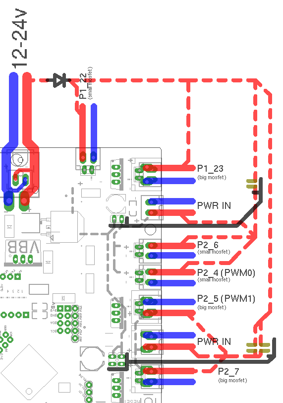
There are three main pairs of Mosfets on the board :
- Big MOSFETS pair : Their outputs are labelled P2_7 and P2_5 on the schematic, the input connector for them is found between them. They are found on the 4X and 5X boards.
- Small MOSFETS pair : Their outputs are labelled P2_6 and P2_4 on the schematic, the input connector for them is found by their side, between P2_6 and P1_23. They are found on all of the boards.
- Mixed MOSFETS pair : Their outputs are labelled P1_22 and P1_23 on the schematic. The pair is called "mixed" because it consists of one big MOSFET and one small MOSFET. They do not have a specific input, they take power directly from VBB ( the Stepper motors power input described in the Stepper Motors chapter ).
MOSFET power inputs have a polarity, make sure you connect + on that connector to + on your PSU, and - to - on the PSU. Heater elements however do not have a polarity, so you do not have to worry about polarity on the outputs. If you are using another output element like a Peltier or a Spindle, you need to be careful to respect the polarity for the outputs too.
Big MOSFETS can handle up to 20A without cooling, but the 5mm green connectors are rated up to only 12A, and the Small MOSFETS can handle up to 3A, and their connectors are rated up to 7.5A. Therefore, never use the big MOSFETS for more than 12A ( and monitor connector and MOSFET temperatures at that current use ), and the small MOSFETS' use should be limited to small fans. Trying to power a 40W hotend cartridge heater at 12V with the small FETs will destroy them, locking them to the "ON" state.
If you need to control more than 12Amps, you can not do it with one of the MOSFETS on board, however you can use a Solid State Relay. For information see the Solid State Relay Appendix on this page.
In the case of both the Big MOSFETS pair, and the Small MOSFETS pair, you take power from the PSU to them via their respective power input connectors.
There is an alternative however. For each pair, you can use jumpers ( one jumper for the small MOSFETS pair ( JP28 ), two parralel jumpers for the two big MOSFETS pair ( JP11 and JP27 ) ). If you solder the pins for those, and connect a jumper to those pins, closing the circuit to VBB ( the stepper motors power input ), allowing you to take the power from those MOSFETS from the same place as the stepper motors do.
In the case of the big MOSFETS, you have to solder and put in place two jumpers, in parallel, in order to handle more current.
Current rating
However, WARNING, each jumper is rated for only 2A of current. This means you can not use this way of powering your MOSFETS if you are going to use more than 2A ( for the small MOSFETS ) or 4A ( for the big MOSFETS, with both jumpers used, for 2 x 2A ).
Do not use the jumpers to power a heated bed for example, as it uses much more than 4A.
In order to configure your Smoothieboard to use a specific MOSFET, you need to know which pin corresponds to which MOSFET. Here is a recapitulating table to help you find that out :
| MOSFET Pair | Big MOSFETS | Small MOSFETS | Mixed MOSFETS | |||
|---|---|---|---|---|---|---|
| Label on diagram | P2_7 | P2_5 | P2_4 | P2_6 | P1_23 | P1_22 |
| Digital output pin | 2.7 | 2.5 | 2.4 | 2.6 | 1.23 | 1.22 |
| Power Input | Between P2_7 and P2_5 | Between P2_6 and P1_23 | Taken from VBB | |||
| Size | Big | Big | Small | Small | Big | Small |
| Maximum current | 12A | 12A | 0.5A* | 0.5A* | 12A | 0.5A* |
| Used for | Hotend | Heated bed | ||||
*While the datasheet says it can handle ~5A, it should not be used for anything but low-current fans, at least at 12V. Trying to run a hotend off of the small MOSFETs will destroy them (experimentally proven at 12V).
Wiring
TODO : diagram
Configuration
Now that you have located which MOSFET you are going to use for Spindle control, and what GPIO pin it corresponds to, you need to add a spindle control section to your configuration file.
We will be doing this using the Switch module
Add this to your configuration file :
#Spindle control Switch module
switch.spindle.enable                            true             #
switch.spindle.input_on_command                  M3               #
switch.spindle.input_off_command                 M5               #
switch.spindle.output_pin                        2.7              # Here we are using the first big MOSFET
switch.spindle.output_type                       pwm              # pwm output settable with S parameter in the input_on_comand
switch.spindle.max_pwm                           255              # set max pwm for the pin default is 255
Controlling the Spindle
Now that everything is configured, you can use G-codes to control the Spindle.
You can do this either manually by sending G-codes directly to the board via serial or your host software, or add those G-codes to the beginning/end.
You can choose the exact G-codes in the configuration, here we used the standard M3 to turn the Spindle ON, and M5 to turn the Spindle OFF.
If you need to choose the power ( speed ) of your Spindle, you can do so because the output is configured as PWM.
Simply do :
M3 S128
To set the spindle to half power/speed. PWM values go from 0 to 255.
Diode
Because the spindle can feed power back into the MOSFET and damage the MOSFET, you also need to wire a diode of sufficient size across the output.
PID loopback spindle control
To get more accurate RPM control, you can use a feedback sensor. This can be optical or a hall effect sensor, which senses the rotation of the spindle. Smoothie then measures the real RPM of the spindle and adjusts the PWM value accordingly.
To use this module, you need to connect your spindle to pins with proper hardware support:
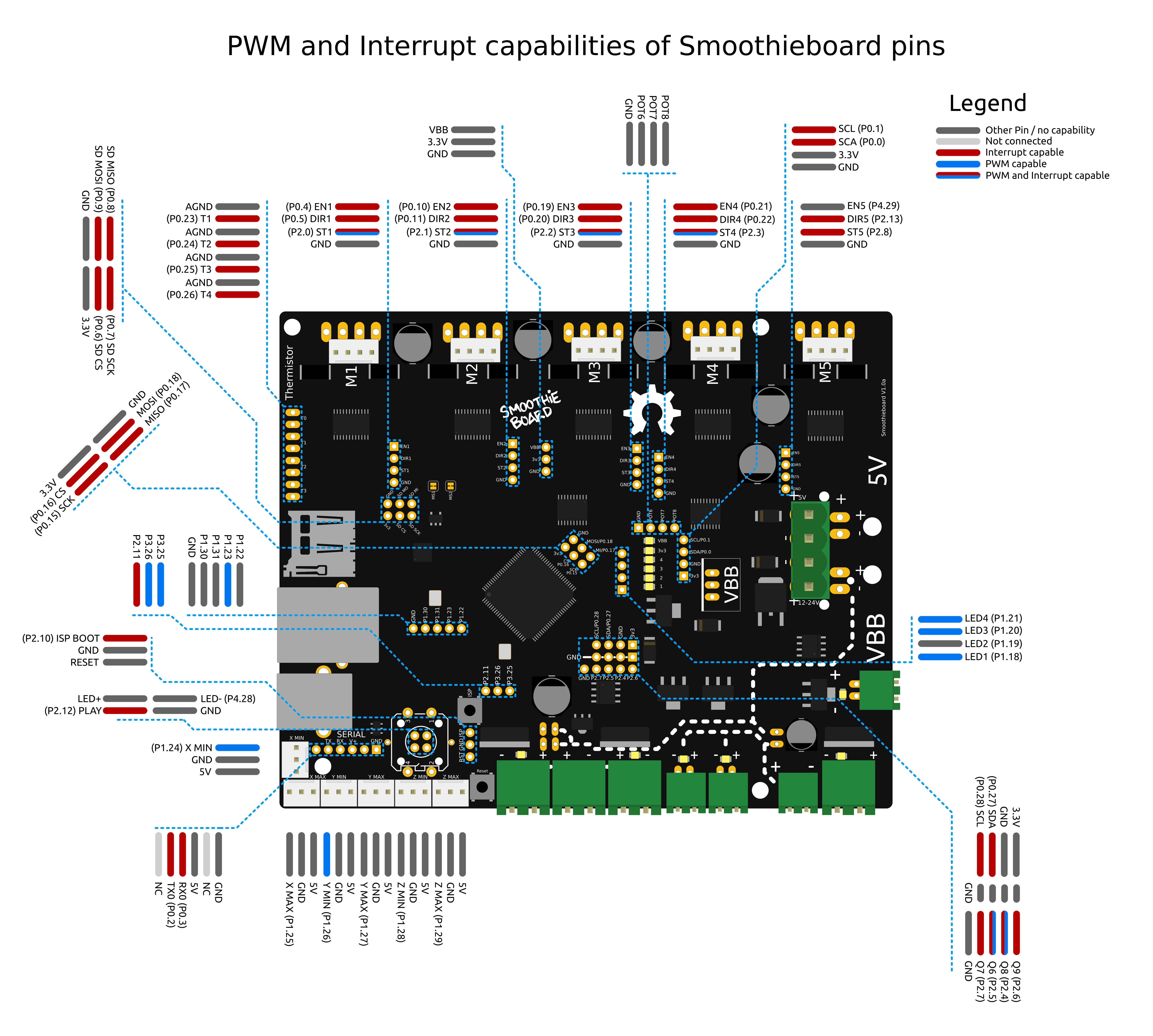
- PWM output pin: any of P1.18, P1.20, P1.21, P1.23, P1.24, P1.26, P2.0 - P2.5, P2.26, P3.25
- Feedback sensor pin: must be in port 0 or port 2; P2.6 and P2.7 are available on smoothieboard
Configuration
| Option | Example value | Explanation |
|---|
| spindle_enable | true | If set to true, enables the Spindle module, which uses an encoder to PID-control a PWM-modulated spindle motor |
| spindle_pwm_pin | 2.4 | Output PWM pin (uses hardware PWM). Note : hardware PWM is available only on pins 2.0 to 2.5, 1.18, 1.20, 1.21, 1.23, 1.24, 1.26, 3.25 and 3.26 |
| spindle_pwm_period | 100 | PWM period to use in microseconds |
| spindle_feedback_pin | 2.6 | Feedback input pin (must be Port 0 or 2, meaning the pin number must be 2.x or 0.x ) |
| spindle_pulses_per_rev | 3 | Number of feedback pulses per revolution on the feedback input pin |
| spindle_default_rpm | 5000 | RPM to use if none given in M3 command, in rotations/minute |
| spindle_control_P | 0.0002 | PID P factor (unit is 1 / RPM) |
| spindle_control_I | 0.0001 | PID I factor (unit is 1 / ( RPM x seconds )) |
| spindle_control_D | 0.000001 | PID D factor (unit is 1 / (R PM / seconds )) |
G-code
Available G-code commands:
- M3 will start the spindle. M3 S5000 will start the spindle and set speed to 5000 RPM.
- M5 will stop the spindle. Last set RPM is remembered and used for next M3 command if S argument is not given.
- M957 will report the current spindle speed and PWM value.
- M958 will report the current PID parameters. M958 Px.xxx Ix.xxx Dx.xxx will set them (to save the new values, you need to edit config file manually).
Tuning the PID parameters
There is no PID autotuning for spindle parameters currently. You can use the following process to manually tune the PID:
- Set dummy values with M958 P0.0001 I0 D0
- Stop the spindle with M5 and make sure spindle is ready to run on next M3 command (i.e. power supply is on).
- Run M3 S100000, which should start the spindle at maximum speed.
- Measure the time T it takes for the spindle to reach full speed (using your ears and a stopwatch).
- Check the maximum RPM R the spindle reaches by running M957
Now set the parameters to:
- P = 1/R (e.g. for 10 000 RPM, set P = 0.0001)
- I = 2/(R*T) (e.g. if it took 1 second to speed up to 10 000 RPM, set I = 0.0002)
- D = T / R / 10 (e.g. D = 0.00001)
Some manual tuning may be needed after this. Test speed changes using the M3 command and try loading the spindle to see if it reacts fast enough to load changes.
Appendixes
Drilling canning cycles
Smoothie now supports drilling canning cycles, using the Drillingcycles module
However, if you do not want to use the module, there are solutions to convert those into "normal" G-codes :
- Online converter to convert your files
- Another Online converter
- Python script
- If you are using Cambam you can use this post-processor script
Printing, milling or cutting from the SD card
Printing, milling or cutting from the SD card on Smoothieboard is easy. First, you transfer your gcode files to the card. You can do this by moving the SD card to your computer and copying the files to it or simply copy the files to the card when it mounts on your desktop. If it isn't mounting automatically, you are probably running Linux and have automount disabled. You can change that or manually mount it. The other option is to use the built in Web Server if you have installed the RJ45 connector and an ethernet connection to the board. You can upload files to the SD card with this convenient Web interface.
Now, with your gcode files on the SD card, there are a few options to run it from there :
Serial terminal
You can use a serial port terminal application like CoolTerm (it supports OSX, Windows, Linux) or Cutecom ( OSX and Linux ). Once connected, enter help to get a list of supported console commands.
If you use Pronterface with your 3D printer, you can use its built-in serial terminal feature - just prefix serial commands with an "@". So, once connected to smoothie send "@help" and it will list all of the available commands.
You can find more information about using the play command here.
You can also use the M24 G-code to play files from the SD card, see Supported G-codes.
Web interface
Another option is to use the Web interface mentioned above.
Panel
If you have a panel (like the RepRapDiscount GLCD) you can use the panel menus to run/pause/stop printing your gcode files.
Crimping connectors
If your Smoothieboard came with connectors, you got connector casings, and crimps. You will need to attach your crimps to your cables, and then insert the crimps into the connector casings.
This tutorial is a good read about crimping properly.
Patience
Please be careful and patient, if you have never done it before you will probably fail a few times before getting the hang of it. Also be careful to insert the crimp into your connector the right way around.
Soldering connectors
Please read this comic before soldering anything.
Using two steppers motor on a single driver
Stepper motor drivers on Smoothieboard can handle up to 2Amps per driver.
If you want to control two separate motors with a single driver ( for example you have two stepper motors for your Y axis like on a Shapeoko, or two stepper motors for your Z axis like on a Reprap Prusa i3 ) and have both motors move simultaneously, you have two options.
If the total of the current used by your motors is more than 2Amps ( for example two 1.5Amps motors are 3Amps ), you can not wire them together on a single driver, and you need to look at doubling drivers just bellow.
However, if your total current is less than 2Amps, you can wire both motors in parallel to a single driver.
To do so, find for each stepper motor, which wires match which coils, and wire the same coils into the stepper motor connections on the Smoothieboard ( two wires per connection, one from each motor, for each pin ).
If when you test it, the two motors turn in reverse, you need to reverse one of the coils of one of the stepper motors, and they will start turning in the same direction.
You also need to set a current value for that driver that matches the total current your two motors will be using. For example if the motors are each 0.8Amps, your total is 1.6Amps and you need to set for that specific driver ( here gamma driver is shown ) :
gamma_current 1.6
Doubling stepper motor drivers.
If you need to drive two motors with a single axis, but the total current used for the motors is more than 2Amps ( for example two 1.5Amps motors add up to 3Amps ), you can not wire the steppers in parallel to a single driver and have it control both motors at the same time like described above.
This is the case for example for the Y axis of Shapeoko machines.
In this case, you will need to use one driver for each of your motors. This means you need a Smoothieboard with one more stepper motor driver than you have axes. If you have 3 axes and need to double one, you will need a 4X or a 5X Smoothieboard.
To enslave a driver to another, you will need to connect the control pins for both drivers together.
For example if you want the epsilon ( M5 ) driver to be the slave to the gamma ( M3 ) driver you will need to connect :
- EN3 to EN5
- ST3 to ST5
- DIR3 to DIR5
The connectors for this can be found close to the stepper motor drivers, and are labelled.
Finally you need to do two things in your configuration file :
First, set the current value for both drivers. For example if you are using beta and delta set :
gamma_current       1.5
epsilon_current      1.5
Then, you need to make sure that none of the step, dir and enable configuration values for your slave stepper motor driver, are present in the configuration file.
For example if you are using gamma as a slave, make sure that none of the following values are present in the configuration file :
gamma_step_pin
gamma_dir_pin
gamma_en_pin
If they are, remove them. And be careful, for the delta driver, if you started from the 3D printer configuration file, they are not refered to as delta_xxx_pin but as extruder_xxx_pin, if they are present you must remove them all.
Only remove the lines for the slave driver.
External Stepper Drivers
The logic pins that control the stepper drivers are broken out on all 5 axes to 1x4 pin headers found near each driver on the board. The 4 pins are EN, DIR, STP, and ground. These pins or their equivalents are found on most external stepper drivers. Many drivers call the STP (step) pin PUL (pulse). Some will call the DIR (direction) pin PHA (phase).
Most external drivers have both a + and - pin for each of EN, DIR, and STP. The simplest way to connect the external driver is to wire Smoothieboard GND to all 3 - pins, and the logic pins of Smoothieboard to the corresponding + pins. Note that Smoothie is 3.3V logic and each pin can only supply a maximum current of 4 mA, which is not usually a problem unless interfacing to very large, or very old external drivers which may need a little more.
Pins
While this example will show using the pins of one of the on-board drivers to control the external driver, you can use pretty much any free GPIO pin to control the step/direction/enable pins on your external driver.
All loadouts of Smoothieboard (3x, 4x, 5x) can control 5 external stepper drivers using these ports. The presence or absence of a built in driver will not affect the external driver.

Wiring an external driver with a common cathode
This shows control of an external driver using the pins on the positive side of the external driver's input.
GPIO pins are taken to the positive inputs on the driver, and the ground is shared.
Please note, if your external driver requires 5V, that Smoothieboard only provides 3.3v on it's output pins.
Two solutions to this : either use a level shifter or use the Smoothieboard's pins as Open-Drain ( ie linking to ground instead of linking to 3.3v, when closed ), and wire accordingly.
For example :

Wiring an external driver with a common anode
Here, the 5V is taken from an endstop input's positive terminal, taken to the 5V inputs on the external driver. The step/direction/enable pins on the Smoothieboard are taken to the GND inputs on the external driver.
You will also need to change those pins to be open-drain. To change a pin from being normal to being open-drain, you add a o to the pin's number. For example :
alpha_step_pin 2.0 # Pin for alpha stepper step signal
becomes
alpha_step_pin 2.0o # Pin for alpha stepper step signal
ReprapDiscount Silencio
Reprap Discount has a nice external driver called the Silencio.
It does 1/128 microstepping, so using it with Smoothie makes a lot of sense since Smoothie can do higher step rates.
It comes with an adapter for pololu-type drivers for RAMPS-type boards. However, you can also simply wire it to Smoothie's external driver connectors.
The only catch is : the pins are not in the same order in Smoothie and on the driver's cable. (Note the colors maybe different on your cable)
| Silencio cable color | Black | Green | Red | Blue |
| Silencio connector order | +5v | Enable | Direction | Step |
| Smoothie connector order | Ground | Step | Direction | Enable |
No big deal though, you simply need to swap the step and enable pins in the configuration file.
Also DO NOT connect the Black wire to the 4th pin om smoothie which is gnd on smoothie, it must be connected to a +5v pin elsewhere (eg on the endstops)
Additionally, you need to invert ( by adding a ! to the pin number ) the enable pin ( that's specific to the Silencio )
The step pin does not need to be inverted.
For example for your alpha driver, change :
alpha_step_pin      2.0       # Pin for alpha stepper step signal
alpha_dir_pin       0.5       # Pin for alpha stepper direction
alpha_en_pin        0.4       # Pin for alpha enable pin
to
alpha_step_pin        0.4       # Pin for alpha stepper step signal
alpha_dir_pin         0.5       # Pin for alpha stepper direction
alpha_en_pin          2.0!      # Pin for alpha enable pin
And just wire the Silencio connector to the Smoothieboard external driver connector
Solid State Relays
The big mosfets on the Smoothieboard can handle up to 12Amps. Sometimes that's not enough. Say you want to control a big spindle, a gigantic heated bed, or a tesla coil.
Typical Solid State Relays ( SSR ) can handle up to 40Amps easily, sometimes more. AC ones can run 220V AC, and DC ones up to 60V DC ( typically, look at the specs for yours ).
To control your Solid State Relay ( SSR ), you will need one GPIO pin ( use one of the free ones on the board ideally ), and a connection to GND ( plenty of those ).
A SSR is essentially a big switch : you cut a wire, plug each end of the cut wire into it's two terminals, and then you'll be able to control whether or not those two ends of the wire connect or not. Simple as that.

Wiring a Solid State Relay
You will need to connect GND on the Smoothieboard to the "-" connection on the Input side of the SSR, and the GPIO pin on the Smoothieboard to the "+" connection on the Input side of the SSR.
This example shows using P1.30
Then simply configure the module that will be using the SSR to use that pin, for example in the case of Switch :
switch.misc.enable                   true #
switch.misc.input_on_command         M42  #
switch.misc.input_off_command        M43  #
switch.misc.output_pin               2.4  # GPIO pin we connected to "+" on the SSR
switch.misc.output_type              digital        # just an on or off pin
In the case of TemperatureControl, where you use the SSR to control a heating element for example, there is a catch.
SSRs have a low maximum frequency they can be switched at. You need to specify that frequency or Smoothie will drive it way too fast. In this example, the maximum frequency is 20Hz.
So, you need to modify your module to both use the correct pin ( the free GPIO you wired to the SSR ), and to the correct frequency. Here are the two lines to change :
temperature_control.swimming_pool_heating.heater_pin               2.4
temperature_control.swimming_pool_heating.pwm_frequency            20
Another option, which turns the heaters on/off even less often, is to use bang-bang, where the state is only changed when temperature deviates too much from the set value :
temperature_control.bed.bang_bang            true            # set to true to use bang bang control rather than PID
temperature_control.bed.hysteresis           2.0             # set to the temperature in degrees C to use as hysteresis
                                                              # when using bang bang
Swapping stepper motor drivers
On some boards, you might want to swap two axes.
For example, you have a board that has two connectors on the Z axis, but you want to connect two motors to the Y axis ( which has only one connector ).
In that case, all you need to do is exchange the 3 pin definitions for these two axes.
For example :
beta_step_pin                                2.1              # Pin for beta stepper step signal
beta_dir_pin                                 0.11             # Pin for beta stepper direction
beta_en_pin                                  0.10             # Pin for beta enable

gamma_step_pin                               2.2              # Pin for gamma stepper step signal
gamma_dir_pin                                0.20             # Pin for gamma stepper direction
gamma_en_pin                                 0.19             # Pin for gamma enable
Becomes :
beta_step_pin                                2.2              # Pin for beta stepper step signal
beta_dir_pin                                 0.20             # Pin for beta stepper direction
beta_en_pin                                  0.19             # Pin for beta enable

gamma_step_pin                               2.1              # Pin for gamma stepper step signal
gamma_dir_pin                                0.11             # Pin for gamma stepper direction
gamma_en_pin                                 0.10             # Pin for gamma enable
Now your beta driver becomes your Z axis, and your gamma driver becomes your Y axis
Which pins are which

Troubleshooting
If you run into trouble, something doesn't work as it should, head over to the Troubleshooting page for a list of common problems and means of diagnosis.
You can also contact the Community for help if you can't find an answer in the documentation.
FAQ
- I have a Shapeoko 2 Desktop CNC Mill and the Y axis has 2 steppers on the same driver, will that work?
- The drivers can only handle up to 2 amps (cooling might be required at 2 amps). If you are using NEMA 17 steppers, you should be fine (might want to bump up the amperage to something like 1.8A). NEMA 23 motors typically pull more amperage than a single driver can handle, you are going to want to separate the Y axis steppers out on separate drivers. See the next section for details
Configuring further
The defaults in the config file are sufficient for testing. You'll probably want to turn down the acceleration, however. Depending on your machine type, a good recommendation is 25mm/second^2.
You'll also want to disable the extruder_module, laser_module, temperature_control.hotend, and endstops if you don't use their respective functions.
Testing
You should be able to connect and issue Gcode commands to your CNC mill with Pronterface. This'll allow you to jog your motors and see whether you've wired and configured everything correctly
Software
All software bellow either knows how to interface with, or how to generate g-code for, Smoothieware.
3D Printing
- Slic3r - 3D printing slicer
- Cura - 3D printing slicer and host.
- Pronterface - 3D printing host. See the guide on the Wiki : Pronterface
- 3Delta Printer Control - 3D printing host especially suited for delta printers.
- OctoPrint - Awesome web interface for 3D printer control. On the wiki : Octoprint
- Simplify3D - Closed source 3D printing slicer and host. On the wiki : Simplify3D Requires post-processing of gcode to use on smoothie, see http://mikk36.eu/SimplifyS3D/
CNC
- bCNC - Open-Source CNC host with great preview and other operations. Set machine type to smoothie. and add grbl_mode true to your smoothie config.
- OpenSCAM.org - Open-Source Simulation & Computer Aided Machining (Free 3-axis CNC Simulator which understands G-Code)
- OpenSCAD.org - Open-Source CAD software.
- GCode plug-in for InkScape - Output GCode from SVG files in Inkscape.
- PyCAM - Open-Source CAM software.
- More links at ShapeOko.com.
- jscut - Open-Source in-browser CAM software.
- CamBam - Closed-Source, but cheap and feature-full CAM software. Widely used by hobbyists.
- Fusion360 - Closed-source, free for hobby/fablab/small business.
Laser
- GCode plug-in for InkScape - Output GCode from SVG files in Inkscape. Video tutorial.
- Visicut - Full laser control application, has Smoothieware interface. Video tutorial.
- LaserWeb - Web-based full laser control application, has Smoothieware interface